I want the ability to stuff a can cap with whatever modern caps I want and retain the vintage appearance. Also, the ability to recap it again to put in new ones and/or change the values at will, which is possible with a restuffed can without spending a fortune.
I picked up a couple of "NOS" quad caps on Flea-Pay to see if I am able to empty out the cans neatly. There are a number of different techniques online for doing it. I'd like to be able to open them up again later for servicing and/or adjustment. We will see how it goes. Step 1: Empty the can without ruining the appearance. Step 2: Find a use for them, which I am sure will be no problem in the future. How many of us ever have trouble coming up with a new project? 🙂
In the ST-35, biased almost into true class A (ideally zero current draw change with signal level), this doesn't matter enough to matter.
I agree with you. The current model ST-35 is supposed to have about 12.6 to 13 watts dissipation, as mentioned previously. I also ran it through the bias calculator here, which is pretty nice: https://robrobinette.com/Tube_Bias_Calculator.htm
However, I notice that the Tronola article about the SCA-35 states clearly that it is class AB1 (excerpt below). Is it different from the ST-35 in that respect?
SCA-35 article: http://tronola.com/html/a_new_look.html
The subject of amplifier classes of operation is blurry at this level of scrutiny. A truly "class A" amplifier conducts over 360 degrees of signal, getting squeezed at the low current end and being limited by grid current at the high current end.* Valves in typical audio amplifiers don't ever really get to Zero current, but instead approach it rapidly at the low current end. Single-ended amplifiers need to stay further away from the squeezed end than push-pull amplifiers because they don't have compensation from another valve operating at opposite polarity (and opposite polarity non-linearities summed together).
*An ideal class A stage has no distortion, so no change in current draw from B+. All real amplifiers have some.
Now draw an operating loadline (a single valve's loadline can illustrate the point.) As we move the loadline down (more negative G1, lower current) we encroach on the squeezed together curves down at the bottom. At no point does current actually go to Zero, but at some point we say that we have Class AB1 operation. It's a judgement call, where with a single valve distortion becomes unacceptable. This inflection point is a "soft limit" to valve current**; beyond here a push-pull amplifier's transfer curve asymptotically approaches a different loadline, one where sometimes only a single valve is contributing. In semi-con amps this is called transconductance doubling (because looked at from the other end - we would call it transconductance halving).
**There is no actual such thing as class B; it's just a theoretical construct. Real amplifiers with almost no idling current transition from class C to class AB, with resulting crossover distortion.
Because of this different loadline, more current is drawn from the B+ supply in this region. So for every case, some current draw variation is applied to the power supply. A matter of degree - the lower the idle current, the greater the current draw variation for a given output.
Original ST-35s operated the output valves very hot, nearly class A for full output, and truly class A for the vast majority of signals. Only peak output, near clipping, transitions into class AB (as we define it). The price to be paid is in heat, but vacuum valves have the ability to operate at ridiculous temperatures - oxide cathodes run about 1000K.
There are two more relevant topics, the time constants of the B+ supply, and the time constants and interrelatedness of bias voltages with signal, that others will need to comment on.
All good fortune,
Chris
I didn't answer your question about the SCA-35 bias. They are exactly the same as classic ST-35s in that respect, same transformers, B+ cap values, cathode bias resistor and cap, etc. The ST-35 PCB fits in an SCA-35. D. Gillespie's EFB, in addition to its sliding bias, sets output valve idling current at a nominal 27mA per valve IIRC, cooler operation than the original 35-or-so mA, for better life with modern valves and modern line voltages. The bias time constant with signal level is also changed, although this isn't a priority issue for his design.
All good fortune,
Chris
All good fortune,
Chris
Chris, thanks so much.
At a certain point, an ST-35 ceases to be an ST-35. I think Hafler would have put a choke in the available chassis space were it not for price, and it doesn't change the design really, so I think that's an easy choice to add that.
I likely will use the available bias kit that allows individual tube bias tweaking despite all of the vocal proponents of the single, regulated voltage approach stating that it's the "best" way to go. One bias setting, even if regulated, for 4 tubes doesn't make much sense in my mind, and I really don't want to stray too far from the original ST-35 design. IMHO that power supply board makes the ST-35 something other than an ST-35, replacing the quad cap, blocking the spot for the choke, and if you are correct then also reducing the idle current to try to extend tube life.

We seem to have similar design aethetics, so maybe I could persuade you to spring for the cage, while they're available. US$50 is a bargain price and your heirs will appreciate the added value. But mostly, it's also a safety issue. Nobody cares about your skunky butt or mine, but children, pets, visitors - why take any chance when it's so easy to protect from little fingers? 'Nuf said.
All good fortune with your project,
Chris
All good fortune with your project,
Chris
$115 plus shipping for the tube cage. The amount of time that the cage has spent on top of my ST-70 series ii over 30 years is approximately 10 minutes (or less). My amps are in a ventilated cabinet behind glass doors, and I am planning to put teflon tubing over the few leads on the PCBs where potentially shocking voltages may be present to reduce risk (to me) as I reach around in there sometimes. The heat of the tubes is enough generally for me to keep my fingers out of there. I may order a tube cage anyway, to sit on the shelf collecting dust next to the one for my ST-70 ii. I do like to leave them off for three reasons: 1) I got in the habit when the ST-70 ii had constant red plate issues - new out of the box and after warranty repair twice - before I gutted and rebuilt it, and 2) I do like the glow of the tubes, and 3) The sides of the cage are solid, holding in the heat. I wish they were perforated.
Really, this project (which I haven't even started) isn't about the aesthetics of the ST-35 but the original sound. After a whole bunch of mods, like completely replacing the power supply with a totally different design, it turns it into something other than an ST-35. I am debating using the old-style carbon resistors instead of metal film. Horror, right! 😲
Since the owner of MagneQuest passed away 3 weeks ago, identical new OPTs are no longer available. The ones from DynaKitParts are supposed to be the same in every respect except that they have 8/4 ohm taps instead of 16/8, which means that technically they are not identical. All others on the market are "substitutes" not identical, and all are oversized per my investigations so far.
https://www.facebook.com/people/MagneQuest/100054351979647/
To get some of that same sound from the ST-35 that many owners heard . . .
get a pair of original Dynaco A-25 speakers.
600,000 Dynaco A25 speakers
get a pair of original Dynaco A-25 speakers.
600,000 Dynaco A25 speakers
600,000 Dynaco A25 speakers
I owned and enjoyed the Smaller Advent Loudspeaker for many years. A classic. I went almost directly from there to the Klipsch Heresy II, which I finally powered with the Dynaco ST-70 series ii, which as anyone who has read this thread knows was a fatally flawed amp that had to be gutted and rebuilt. The only other thing I changed in that system was wiring the Heresy II crossovers point-to-point using solid copper wire following the circuit board traces, which I considered a really bad design choice by Klipsch. The ST-70 plus Klipsch Heresy = vintage sound, good so long as the Heresy II was backed up against the wall or in a corner. Otherwise, as we all know, not much bass from the Heresy II.
My current speakers, which I designed and built roughly 30 years ago after countless hours of calculations and several test builds, are substantially based on the physics and acoustics described by Paul Klipsch in his early technical writings. It is entirely possible to design and implement speakers based on his ideas without using horn/compression drivers, which I did. I am about to repower them for the third time with brand new drivers. If I had found a speaker solution that I thought was better, I would have implemented it by now. Note: In a real living room inhabited by real people, speakers have to go against the wall. Design and choose speakers accordingly. 😉
speakers have to go against the wall. Design and choose speakers accordingly. 😉
Really, this project (which I haven't even started) ...
Well, it is now started. Everything for a new DynaKitParts ST-35 has been purchased except the tubes.
Now I have to make some decisions on the power supply. I did order the optional choke, so I'll be using that. I also ordered the bias adjustment add-on kit with the four trim pots, one for each tube.
The kit comes with a 60/40/20 uF 450VDC can cap. However, I may use this to make my own cap instead:
It's a mint condition quad cap can that I cleaned out perfectly, leaving all of the terminals intact. I can now stuff whatever values I want inside and change them relatively easily in the future since I'm not going to crimp the can shut again.
The largest values that will fit would be this arrangement:
Any thoughts on these capacitor values? I haven't made a decision yet. I may insert a series 50Ω 5W resistor between the diodes and C8A as discussed previously, to drop about 25 volts, but I haven't made that decision either.
I'll be using 6P14P-EV output tubes. so the voltage and dissipation is not a large concern. They are built to handle it. Also, tube life in this amp never has been a large concern for me. There are no complaints about it with the amplifier as-is with no changes, just theoretical discussions of what might affect tube life with no actual data and no first-hand experience to back up those ideas.
I have opted for the bias board that allows individually tweaking the bias of each output tube over its lifespan, but I don't want to modify the original design much farther than that.
My question now is, given the original design and me not being concerned with reducing the voltage and dissipation much if at all, what would be the optimal cap values for me to put inside the empty can for the power supply. It seems that most designers follow the "bigger is better" approach with these caps.
If I want to reduce voltage and dissipation, (and I am not sure that I do) I never have understood why reducing or removing C8A instead of just putting a series resistor between the diodes and C8A wouldn't be an excellent (and easily reversible) approach. It would allow me to jumper the resistor in and out of the system for A/B comparison also, giving me a choice of "jumped out of the circuit sounds better and/or has more power" but "un-jumped to put it in the circuit may extend tube life by an unknown amount." In PSUdesigner, reducing the value of C8A actually has little effect on the voltage. There is plenty of room for a nice resistor to be mounted on top of the chassis where it can breathe, its power consumption and heating are a non-issue, and it could be jumpered in and out if desired. The original design even uses a 50 ohm resistor, just placing it after C8A where the choke now will be rather than me (possibly) placing it before C8A.
The individual bias adjustment add-on board schematic:
Last edited:
Tube life can be affected if they work on maximum dissipation.
I have EL84 PP - the tubes are working on max.
First set were 6P14-EV and they lasted the longest with graceful weakening. At one point they measured ok and six months later they measured as weakened - but this I would not notice just by listening.
Next quartet were Ei EL84 - they lasted around 5,000 hr by my conservative calculation before one tube on the left channel started to work the job of almost two tubes, the other weakened much more. The other pair was not nearly in such a bad condition but was ready for change.
BTW the tube in badest condition needed it's socket changed - did this affect things in some measure - don't know.
The amp has auto bias in output stage and each tube has a resistor for checking current - I just totally forgot about this because I have excellent serviceman for this amp.
Anyway I used by now 6P14-EV, Ei EL84, Tungsram EL84 - from these the old Soviet ones are more robust ( at least in such working conditions ), the Ei & Tungsram are excellent if You can find really good NOS samples.
Regards, Krca
The resistor before the first cap will have more dissipation than you might think, as the current there is discontinuous with high peaks. I suggest you model the circuit in PSUD and use the RMS current in the resistor to figure dissipation. It'll be considerably higher than the average current.
Consider the following:
1. The Golden days of audio (before many were even born):
Power Mains were 110V or 115V, or perhaps as high as 117V.
Vacuum tube rectifiers were used for B+ (with the plates acting as a series resistor).
The power transformer was designed to work with the above facts.
2. Todays modified designs of those Golden days audio amplifiers, and using the original old power transformers:
Power Mains are often 117V or 120V, or perhaps as high as 123V.
Vacuum tube rectifiers are being replaced with low voltage drop silicon rectifiers with less than 1 Ohm of series resistance.
The first filter capacitor is being replaced with higher capacitance than the old tube rectifier first filter capacitors.
Improvements, not without problems.
What happens to the original power transformer (or an exactly specified replacement)?
It says: Ugh! I am getting so Hot!
The old power transformers were Not designed to work with the above facts.
Just My Opinions
(and my personal experience; I run my old transformers at lower current of both B+ and filament current; I even use the much friendlier choke input filter for B+).
My transformers run cooler, not hotter.
82uF first filter cap, and 1.75H choke does not come within a Parsec of what a real choke input filter is.
A Parsec is an extremely large distance, a common term for Astronomers.
Last edited:
I bought and built the Dynakit ST-35 a couple years ago. The mods I made were replacing the RCA jacks, replace the 50ohm resistor with a 62 ohm choke Dynakit sells. There is an extra hole in the Dynakit chassis just for mounting the choke.
I also installed the Dynakit bias board. I used speaker spikes for feet to get some better air flow. Taller rubber feet would work. I'm using Sovtek EL-84M's and JJ driver tubes. I do have some Reflecktor 6P14P-P's I put in a single ended amp I built, and a quad I put in a modified Magnavox 9303 amp. They sound pretty good. I may try a quad of the 6P14P-EV's in my ST-35.
The ST-35 has been trouble free and sounds great.
Attachments
I bought and built the Dynakit ST-35 a couple years ago. The mods I made were replacing the RCA jacks, replace the 50ohm resistor with a 62 ohm choke Dynakit sells. There is an extra hole in the Dynakit chassis just for mounting the choke.
I also installed the Dynakit bias board
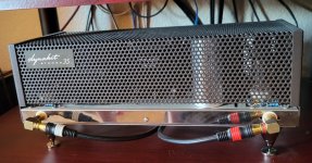
Great! I was hoping that someone here had built one. I will be using the choke and the bias kit, just as you did. Everything has arrived, well packed, but I won't be starting the build for a while. Step 1 will be for me to paint everything satin black. I did buy the black tube cage, but I won't use it. I only bought it in case a future owner wants to use it.
I'm using Sovtek EL-84M's and JJ driver tubes. ... The ST-35 has been trouble free and sounds great.
@lavane
So you are still on your first set of tubes after a few years with no issues?
I knew the amplifier was small, but just how small it is didn't sink in until I got the chassis out of the box. It's only about 5-1/2" deep. The $950 price tag was a but more than I wanted to spend, but I wanted to try one while they are available. It's a very well done kit.
The resistor before the first cap will have more dissipation than you might think, as the current there is discontinuous with high peaks. I suggest you model the circuit in PSUD and use the RMS current in the resistor to figure dissipation. It'll be considerably higher than the average current.
A little over 5 watts. I would use one of the power resistors that comes encased in a finned metal heatsink I guess.
I have EL84 PP - the tubes are working on max.
First set were 6P14-EV and they lasted the longest with graceful weakening. At one point they measured ok and six months later they measured as weakened - but this I would not notice just by listening.
Next quartet were Ei EL84 - they lasted around 5,000 hr by my conservative calculation
Thanks!
Chris,I didn't answer your question about the SCA-35 bias. They are exactly the same as classic ST-35s in that respect, same transformers, B+ cap values, cathode bias resistor and cap, etc. The ST-35 PCB fits in an SCA-35. D. Gillespie's EFB, in addition to its sliding bias, sets output valve idling current at a nominal 27mA per valve IIRC, cooler operation than the original 35-or-so mA, for better life with modern valves and modern line voltages. The bias time constant with signal level is also changed, although this isn't a priority issue for his design.
All good fortune,
Chris
Would you please elaborate on the last sentence. I’m not sure I understand and would like to know more.
Btw, Dave Gillespie stated that he decided to provide a common bias (in the EFB boards for SCA35 and ST35) for all four output tubes because “he did not want to deviate too much from the original Dyna design”. But he also added a plausible explanation of the advantages of having a common bias (in addition to the known disadvantages). The primary goal was lowering of distortion with the EFB, not preservation of tube life.
- Home
- Amplifiers
- Tubes / Valves
- DynaKitParts ST-35 power supply mods?