Then, after an hour of operation in a warm room, see how hot the EL84 tubes are and how hot the power transformer is (Summer is coming).
It couldn't POSSIBLY run any hotter than my Dynaco ST-70 series ii (Panor Corp. 1993), which is like having a roaring fireplace in August. I have been happy (thrilled) with that amp for 30 years, with 20 of those in daily use. However, the heat in the room no longer is acceptable. If it were, I'd go right on using my Dynaco ST-70 series ii, maybe putting new PS caps in it after 30 years.
Heat-related amplifier longevity and tube longevity issues are not necessarily my concern. The amp doesn't need to last 50 years and the tubes don't need to last 10,000 hours. A 10 year amplifier life and 1,500 hours per set of ouptut tubes would be just fine and dandy, so long as it doesn't throw off as much heat as my Dynaco ST-70 series ii.
I think the kit has been on the market since 2006, and I see no reports of amplifier failure or required modifications or amplifier design changes since then. It's probably just fine as-is given my stated expectations.
Last edited:
I’m curious about the reason(s) for your resolve not to use the external board Dave Gillespie designed to fit nicely in the available space. It gets all the heat-generating PS resistors and regulator outside the case to reduce heat build-up. If you don’t like the looks of it you could put your cage back on and fuggitaboutit. I like it and the results it produces, but do wish Dave had used a regulator for each output pair though.If I were smart enough to figure out how to fit EFB inside the chassis like Art Grannell did, I might do it, but I will never use the giant external EFB power supply board that is now sold, which spans the whole width of the amplifier.
Francois G,
And there you go, individual bias for each tube.
Just like I said.
My old Dyna ST70, with 2 bias pots for 4 tubes taught me that. No fun.
Even with Very Well Matched output tube pairs.
Turn one bias pot, to adjust the cathodes current of one channel, and the other channels current changes too (unregulated B+)
Two pots: back and forth and back and forth and back and forth.
OK, even modified to use 4 pots: back and forth and back and forth and back and forth.
Individual Fixed Adjustable Bias . . . Now where did I put the Aspirin and Water?
Instead, Very Well Matched Push Pull pairs, and individual self bias resistors work.
With brand new tubes, it generally matches very well many years later.
Plug and Play
Can any of you accept a 0.5 dB or 1 dB power loss?
If so, convert from fixed adjustable grid bias to self bias.
Worried about 1dB less power.
Remember this, The old rule said: "If you need more amplifier power, purchase a new amplifier that has at least a 3dB increase of power".
That works both ways, 1dB less power will not make a significant difference.
Use any method that works for you, no matter how easy, or no matter how complex.
Have fun!
I am keeping my 7 year old car. No automatic self stopping feature, no automatic self driving feature.
Driving is a function of Trust and Verify. It is not Trust, Trust, Trust.
Just my opinions
Last edited:
Not to throw a wrench into the works here but another option to drop voltage and get adjustable bias is back bias. The bias will move around based on current like cathode bias but the idle point can be set exactly.
https://www.aikenamps.com/index.php/what-is-back-biasing
https://www.aikenamps.com/index.php/what-is-back-biasing
There is a downside to these attempts to make the power supply less "perfect" - voltage regulation, meaning the power supply's ability to keep a constant voltage with varying current loads, is significantly decreased. In the ST-35, biased almost into true class A (ideally zero current draw change with signal level), this doesn't matter enough to matter. In other amps, it could matter a lot, so yours is a special case.
I will be using the optional choke. There is room for it on the chassis. The kit is designed for it to be added easily, and in PSUDesigner, it makes a big difference. With the choke in the circuit, and an almost continuous load, I am wondering if my original question about increasing the capacitor sizes is even relevant. With the choke in the circuit, the stock 60/40/20 can cap produces almost no ripple in PSUDesigner. As you pointed out, the load is almost continuous, so building up a massive reserve of extra added capacitance in this particular case would seem to serve no purpose unless I am missing something.
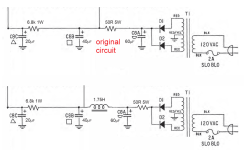
As for the possibility of reducing the B+, I likely will just select robust output tubes like the Sovtek EL84M, which is built for this situation. There are no widespread complaints about tube life with the amplifier. However, it seems that adding a chassis-mounted 50Ω power resistor between the diodes and the first capacitor would drop the voltage just a little bit without sacificing any performance other than heat loss and the cost of the resistor, agreed? A 50Ω 10W in a nice metal housing that would attach to the chassis only costs a few dollars and it's an extremely simple addition and completely reversible, if this solution would work to reduce B+ a little bit. Not sure if I'd need to change the value of that 6.8kΩ but that's easy enough if needed. The 50Ω as shown in the bottom diagram should make the job of the power transformer a little easier too, correct?
Attachments
Last edited:
Looks like you've nailed it down pretty tight. You might explore exchanging the 40uF and 60uF caps in positions C8A and C8B in PSUD to see if you can live with the slightly reduced B+ or not. More C8B is more better, but given the givens, not crucial. Have fun! It'll sound great.
All good fortune,
Chris
All good fortune,
Chris
You might explore exchanging the 40uF and 60uF caps in positions C8A and C8B in PSUD
Yes, I did try that swap, and it did make a little bit of difference, but really not very much, only a few volts. Various values of new quad caps are now available, including the option of "restuffing" a metal can salvaged from a bad quad cap, but since a nice new 60/40/20 comes in the kit, I figure I might as well just use that. Note: Given that modern 450VDC caps have gotten relatively small, it's easy to strap an additional one or two underneath the quad cap to add value to C8B or C8C if there is any room for improvement there. I'm wondering if there is any real improvement to be had there though.
For future reference, an outfit called Hayseed Hamfest custom makes multi-section can caps in beautiful stainless cans, 105C Nichicon caps at a fair - not "audiophile" - price. Very highly recommended.
Chris
Chris
For future reference, an outfit called Hayseed Hamfest custom makes multi-section can caps in beautiful stainless cans, 105C Nichicon caps at a fair - not "audiophile" - price. Very highly recommended.
Nice! I am bookmarking their site for future reference. A lot of people restuff their old can caps, but it requires patience and time to do a good job. Somebody ought to just sell the empty cap cans and bases. Hint: perhaps there is a business opportunity for anyone who wants to find and sell the cans.
I am always amazed by these companies which manage to live on such restricted markets, in France it has become almost impossible with our taxation and it is very regrettable.
Thanks for the info, I'll keep it in my archives.
Thanks for the info, I'll keep it in my archives.
including the option of "restuffing" a metal can salvaged from a bad quad cap
Anybody here got a 1-3/8" x 3" quad cap they don't want? It would be gutted and restuffed, so it need not be functional, just very nice looking cosmetically and with clean undamaged terminals. Somebody ought to sell new empty cans, but apparently not.
Several suppliers of quad caps exist, they sell fully functional quad caps of various capacitances.
Yes, I know. That's not my goal. I want the ability to stuff a can cap with whatever modern caps I want and retain the vintage appearance. Also, the ability to recap it again to put in new ones and/or change the values at will, which is possible with a restuffed can without spending a fortune. A very nice DIY option to have on hand. I may not use it right away, but I want one to have on hand gutted and ready to go for future projects. I can pick up a new condition quad cap on Flea-Pay I guess. The values don't matter since it's going to get gutted.
Last edited:

I've made a bad error here. Don't know where I got the idea that the EFB board provided individual bias to each output valve, but that's wrong. A single bias for all four valves is fatally flawed IMO.Your adjustable-individual-cathode-resistor board is an improved version of that, and the EFB board is just an automatic version of that.
For SCA-35 owners, the ST-35 boards fit physically, but the lower sensitivity means you'd need to bypass the lossy "tone stacks".
All good fortune, and sorry for the error.
Chris
Don't know where I got the idea that the EFB board provided individual bias to each output valve, but that's wrong. A single bias for all four valves is fatally flawed IMO.
I understood what you meant. I have confirmed that the bias upgrade kit from DynaKitParts replaces the single bias resistor and cap with four resistors, four caps, and a trimmer pot to allow minor adjustment for each tube. It fits neatly in place with the choke and the can cap - see video. The fourth section of the quad cap, the one used for bias, is disconnected with the bias upgrade kit installed.
You have to admit that the whole DynakitParts amp kit is a very nice product, with all brand new parts, nothing recycled or reused. Not sure if I want the tube cage or not. The one for my Dynaco ST-70 series ii has spent a grand total of 0 minutes installed over the course of 30 years.
https://www.dynakitparts.com/shop/st35-bias-control-upgrade-kit/
Last edited:
Probably, this is what I was remembering:
http://www.tronola.com/html/ps_mods_for_st-35.html
All good fortune,
Chris
http://www.tronola.com/html/ps_mods_for_st-35.html
All good fortune,
Chris
Yes, that is the one. One regulator for four tubes. Art Grannell also published it as a tiny, completely internal mod using only a few components. http://www.tronola.com/html/efb_in_a_dynaco_st-35.html The internal version by Art is an interesting tweak for those wanting to keep single bias for all four tubes and also keep the external appearance 100% stock. The current offfering is a board spanning the whole width of the amplifier, replacing the quad cap, adding a giant heatsink for the regulator, and blocking the space otherwise available for a choke. For people who want to run the amp with no tube cage, exposed HV voltages appear to be an issue (kids, dogs and cats, guests, fat fingers, accidents, etc.) The one regulator is for all four tubes. It looks like this:

The alternative is the bias kit from DynakitParts.com with individual tube bias, including trimmers for each tube. https://www.dynakitparts.com/shop/st35-bias-control-upgrade-kit/
It looks like this with everything installed including the choke, which fits perfectly on the chassis.

The alternative is the bias kit from DynakitParts.com with individual tube bias, including trimmers for each tube. https://www.dynakitparts.com/shop/st35-bias-control-upgrade-kit/
It looks like this with everything installed including the choke, which fits perfectly on the chassis.
Cage is needed on all of the above st35 as high voltages are present in EFB, dynakit-individual bias and an
unmodified ST35. No difference here.
The EFB is the only variant where the can cap is totally replaced with modern board-mounted caps.
Getting well matched EL84 is a trivial task, i do not see the point in adjusting dissimilar tubes , it's like
mounting dissimilar tires on a car, adjusting the suspension to fit.
... i do not see the point in adjusting dissimilar tubes, it's like mounting dissimilar tires on a car, adjusting the suspension to fit.
It's like the prudent practice of "rotating" identical new tires that wear unevenly over time due to real world imperfections in the tires and the alignments, and also correcting minor out-of-alignment issues that occur over time, except that it's worse in this analogy because one slightly worn "tire" radically accelerates the wear of the other three until a "wreck" occurs. I practice tire rotation and also have the vehicle alignment checked and adjusted as necessary to prevent issues.
B+ is not present on the individual bias board, only minor voltages (less than 15 volts). The few leads on the PCBs that have over 100 volts will be protected with teflon insulation and/or heat shrink to reduce risk, and the heat of the tubes is a tremendous deterent to keep fingers out of there on top of that. The board from Tronola appears to expose the full voltage from the power transformer and diodes right up front on the amplifier. I had a friend poke a soft dome tweeter one time to see what it felt like before I could stop him. Don't try that with that power supply board.
That board also prevents the use of the choke since it blocks the whole front of the amp. I will be using the choke.
Last edited:
If you are not interested in the performance enhancement provided by EFB, perhaps you should take a look at this new single PCB offering with individual output tube cathode bias-adjust built into the circuit. The seller also offers a nice stainless steel top plate at a reasonable price.
https://www.ebay.com/itm/2250663174...Sa8BgLrRxy&var=&widget_ver=artemis&media=COPY
https://www.ebay.com/itm/2250663174...Sa8BgLrRxy&var=&widget_ver=artemis&media=COPY
- Home
- Amplifiers
- Tubes / Valves
- DynaKitParts ST-35 power supply mods?