All rigth Simon...girls are nice....hummmm!... great!
Your connections are perfect..diagram nice...... good!
I like that too....for sure i like (girls)
regards,
Carlos
Your connections are perfect..diagram nice...... good!
I like that too....for sure i like (girls)
regards,
Carlos
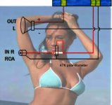
Please Simon.... install potentiometers.... two 47K in the input
This way the amplifier will be complete...i am using your image (with your licence of course) in the Brazilian forum.
regards,
Carlos
This way the amplifier will be complete...i am using your image (with your licence of course) in the Brazilian forum.
regards,
Carlos
Attachments
Last edited:
Ok. I'll edit the diagram for a single volume pot double gang. Should it be logarithmic or linear?
Regards
Simon
Regards
Simon
It is better to use two single potentiometers..they can be linear or logaritimic
Linear is better.
Using two potentiometers you can adjust volume separatelly, without the need of a ballance control.
Dual gang can be used...but you gonna lost this feature, to adjust each channel.
In the reality it is a matter of preference dear Simon...it is up to you.
Shalom.
Carlos
Linear is better.
Using two potentiometers you can adjust volume separatelly, without the need of a ballance control.
Dual gang can be used...but you gonna lost this feature, to adjust each channel.
In the reality it is a matter of preference dear Simon...it is up to you.
Shalom.
Carlos
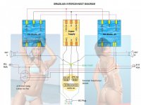
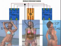
Brazilian Interconnect Diagram
Ok. Here are 2 variants. One with separate left and right volume control and one with dual gang pot single volume control. If maybe Greg is reading this, he could add this to his DX AMP website? This may help simple people like me in the future.
Ok. Here are 2 variants. One with separate left and right volume control and one with dual gang pot single volume control. If maybe Greg is reading this, he could add this to his DX AMP website? This may help simple people like me in the future.
Attachments
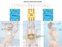
PSU GND <> Audio GND
I disagree.
No audio connection to be made to the PSU centre tap (PSU Zero Volts)
I would suggest moving the two speaker returns to the black dot interconnection shown directly above the Power Supply 0V. This becomes the Audio Ground.
For a normal volume control use a log law pot/s, not a linear law pot.
Now I am a bit confused. Does this mean Andrew that it is better to move the star point to the output side of the Power supply where the black dot connection point is? The input 0V and output 0V are electrically connected anyway so would this make a difference?
Simon
Simon
yes, it makes a difference.The input 0V and output 0V are electrically connected anyway so would this make a difference?
http://www.diyaudio.com/forums/diya...udio-component-grounding-interconnection.html
Do not connect any audio ground to the circuit that carries the smoothing cap charging pulses.
Yep.... zero volt should go direct to the star ground..the transformer secondary
Your dual gang potentiometer is no good.... the variable portion is going to the power amplifier input..observe the power amplifier has a variable resistance depending the potentiometer position.
Transfer that variable resistance to the audio source...left the power amplifier with the potentiometer extremes..the way i have shown you in my diagram.
The power amplifier, depending your volume adjustment (zero) will have it's input short circuited to ground..... it is prefered to short circuit to ground (for signal) the audio source equipment.
Image is the way i like...despite your way will work too... even without the chassis grounding i had no noises too.... do not worry too much because it is not usual to have problems.
All ground wires should join the power transformers center tap.... this is the main need.
regards,
Carlos
Attachments
Last edited:
DX advice is wrong.Your dual gang potentiometer is no good.... the variable portion is going to the power amplifier input..observe the power amplifier has a variable resistance depending the potentiometer position.
The wiper goes to the amplifier.
Potentiometer = potential divider.
this is bad advice...............All ground wires should join the power transformers center tap....
I am using this way... wiper goes to live from the source
My advice is good...it works.
regards,
Carlos
My advice is good...it works.
regards,
Carlos
I just copied the potentiometer circuit from this web site. Potentiometers (Beginners' Guide to Pots) I was going to play music sometimes through the headphone output of my MP3 player. If the wiper is conected to the input then sometimes the ground will be shorted with the input of the headphones. Would this be good for the MP3 player? I just need clarification before modifying the drawing.
Going by the diagram the Input on the diagram would be from the source and the output on the diagram would be going to the amplifiers input(is this correct?).
Thanks
Simon
Going by the diagram the Input on the diagram would be from the source and the output on the diagram would be going to the amplifiers input(is this correct?).
Thanks
Simon
Attachments
You can install 22 ohms resistance in series with the potentiometer center tab
Then your worries about short your player to ground (MP3/4) will finish.
I will not discuss the subject anymore...in special because AndrewT landed here, once again, to create disconfort.
You do the way you want..follow Rodd or other instructions.... also you can build his amplifier if you prefere.
I will not debate, argue or discuss about things i use in real life...about solutions hundreds of my friends have used in their Dx amplifiers, that proved to work fine.
What Rodd said or published or others..are their problem...what i publish is the result of tests..and if worked real life this closes the subject to discussion.
regards,
Carlos
Last edited:
Brazilian soft start revised by the Brazilian group
I have people helping me...designers are creating these circuits published for our information only.
I have not created the soft start or the protection, others did and have assembled and tested.
100 kits are being offered and already ordered in Brasil..including power supply boards, amplifier boards, soft start against current sourge and Protector boards, with thermal sensor, delay to insertion, fuses, DC off set sensor and other features.
regards,
Carlos
Attachments
Audio sources including MP3-players are voltage sources, and therefore ideally have zero output impedance (resistance). The only way to force them to reduce their amplitude of output voltage (other than reducing the volumesetting of the source itself 😉 ) is having them work into a short circuit. Usually this wont harm the source, because it should have a protection against the short cicuit condition. But it is not the intended mode of operation. Especially trying to reduce the volume like this will introduce serious distortion to the signal, because the short circuit protection becomes active and clips the voltage.
If on the amplifier side of the potentiometer the input of the amp has a parallel resistance to ground, then connecting the wiper to the output of your audio source places a variable resistance in series to the input, which will form a voltage devider with the afore mentioned fixed resistance in parallel to the input. So turning the poti will reduce the signal amplitude to some extent (depending on the ratio of the two resistances) but will not reach zero, until the source is being shorted by the potentiometer.
the most common practice is having the wiper go to the input of the power amp as shown in the image attached to post#255
Last edited:
Build a Dx Amplifier folks.... a very pleasant sonics
to the joy of your life.
Now you can etch at your own home using Todd Johnson's Layout....you have the German group lovely board and now a days Brazilians have produce another board too.
So, all them tested and aproved by several guys..... one more month and we gonna reach 140 happy builders of Dx Blame amplifiers and almost 400 amplifiers made, all them designs from the Dx Corporation, the virtual enterprise of happy dyers.
Give yourself the chance to be happy too...build an amplifier...build the amplifier.
Dx Blame ST.
Carlos
.....................................................................................................................
The picture:
Arabians produce oil.... Dx produce good amplifier for your life enjoyment
Attachments

Last edited:
- Status
- Not open for further replies.
- Home
- Amplifiers
- Solid State
- Dx Blame ST - Builder's thread - post pictures, reviews and comments here please.