
Hey USR
PF ... See post #83
And Yeah great idea, i will request to move it.
How the last sim looks compared to the original post #117
PF ... See post #83
And Yeah great idea, i will request to move it.
How the last sim looks compared to the original post #117
Last edited:
Done, moderator renamed the thread.Are u building this topic TH design or a PF design. I'm a bit confused.
It's better to start a new topic instead of 'hijacking' this Pa-TH30hz-extension thread and request a moderator to move the posts to your new thread if that is possible.
more of the same….
…just fills in the depression after the fundamental sides 3/4 harmonic as an added parallel offset entry resonator and appropriate TL stuffing As GM or Martin King would suggest.
I think this is a very basic description of some of the more current paraflex potential models/improvements. However, once stuffing so much and creating multiple resonators and shapes I quickly return to a simple offset entry TL/TP instead. It’s flat AF and ALWAYS consistent thru its own 5/4 harmonic. Additionally it can be tapered or reduced in the last of 3 folds to a ~6.66xFb bandwidth.
Attachments
Last edited:
1. I can't believe I've been missing all these posts. My Outlook/Hotmail has been tripping.
2. Look at you Max, you got the man himself posting in your thread...David McBean!
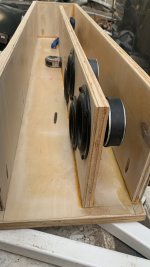
3. Use PAR segments in HR. You are not building a CON enclosure.
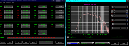
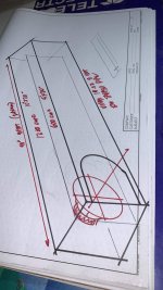
this isn’t a sub, but you can do the same )
green is fundamental
blue is it’s 3/4 and red is the 5/4.
yelliw and area of response that preceeds it is the split resonator that joins in parallel . Look at the lengths and associated freqs.. it all makes ’perfect’ sense
exsmple:
green is fundamental
blue is it’s 3/4 and red is the 5/4.
yelliw and area of response that preceeds it is the split resonator that joins in parallel . Look at the lengths and associated freqs.. it all makes ’perfect’ sense
exsmple:
Attachments
Last edited:
‘I don’t care about above 100hz, it’s a sub’
well what about your crossover slope /outta phase and then resulting integration with other speakers?
it’s not just about 36-108 hz, 32-96 hz or 28.8-86.4 or …. (Whatever length pipe you use and it’s resonances(240cm, 270cm, 300cm) )
in 1/4 - 3/4 wave resonances if you want it to work really really good ? I dunno, but it sure sounds like it to my amateur(at best) ears
Right, we ideally need -25 dB an octave away, though of course what's a dB among friends 😉, so with basic filter theory, -24 dB/octave = 4th order down to 1st order = (4) octaves away, which at some point makes one realize that we need to 'think' in other than 1/4 segments.
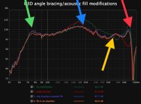
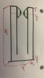
GM , like this(pic) ?
But, Ima math geek out too:
200cm 43.2 hz
66.66 cm 129.6 hz
40cm 216hz
150 cm 57.6 hz
50 cm 115.2hz(52.36 driver entry with end correction, mass loading and corner loading)
30 cm 288 hz
33.33 cm 259.2 hz (xo point shown)
25920 years is ‘the great year👽👽👽sorry, cant resist the temptation to show everything as to ‘time/compass/pi/speed of light/pendulum arc per second /pythago reference so it’s so oBVIOUS as 1/4 wave/season, 90 /180/270/360450/540/4320/8640…etc…. As degrees, freq, wavelengths, universal understanding 👍🏼👍🏼
Attachments
Last edited:
At a glance, guessing not; regardless, please attach HR file for me/us to Import if wanting me to look at HR sims. TIA
ID = 54.10
Comment = NEW RECORD - NEW RECORD - NEW RECORD - NEW RECORD - NEW RECORD - NEW RECORD
|RADIATION, SOURCE AND MOUTH PARAMETER VALUES:
Ang = 0.5 x Pi
Eg = 12.00
Rg = 0.00
Fta = 0.00
|HORN PARAMETER VALUES:
S1 = 150.00
S2 = 150.00
Par = 52.36
F12 = 0.00
S2S = 150.00
S3 = 150.00
Par = 50.00
F23 = 0.00
S3S = 75.00
S4 = 75.00
Par = 47.64
F34 = 0.00
S4S = 0.00
S5 = 0.00
L45 = 0.00
F45 = 0.00
|TRADITIONAL DRIVER PARAMETER VALUES:
Sd = 50.00
Bl = 7.45
Cms = 7.00E-04
Rms = 1.67
Mmd = 10.12
Le = 1.90
Re = 7.80
OD = 4P
|ADVANCED DRIVER PARAMETER VALUES FOR SEMI-INDUCTANCE MODEL:
Re' = 0.00
Leb = 0.00
Le = 0.00
Ke = 0.00
Rss = 0.00
|ADVANCED DRIVER PARAMETER VALUES FOR FREQUENCY-DEPENDENT DAMPING MODEL:
Rms = 0.00
Ams = 0.00
|PASSIVE RADIATOR PARAMETER VALUE:
Added Mass = 0.00
|CHAMBER PARAMETER VALUES:
Vrc = 0.00
Lrc = 0.00
Fr = 0.00
Tal = 0.00
Vtc = 0.00
Atc = 0.00
Acoustic Path Length = 0.0
|MAXIMUM SPL PARAMETER VALUES:
Pamp = 100
Vamp = 25
Iamp = 4
Pmax = 40
Xmax = 4.0
Maximum SPL Setting = 3
|ABSORBENT FILLING MATERIAL PARAMETER VALUES:
Fr1 = 100.00
Fr2 = 50.00
Fr3 = 0.00
Fr4 = 0.00
Tal1 = 0
Tal2 = 0
Tal3 = 100
Tal4 = 100
|ACTIVE BAND PASS FILTER PARAMETER VALUES:
High Pass Frequency = 0
High Pass Slope = 1
Low Pass Frequency = 259
Low Pass Slope = 1
Butterworth High Pass Order = 1
Butterworth Low Pass Order = 4
Linkwitz-Riley High Pass Order = 2
Linkwitz-Riley Low Pass Order = 2
Bessel High Pass Order = 1
Bessel Low Pass Order = 1
2nd Order High Pass Q = 0.5
2nd Order Low Pass Q = 0.5
4th Order High Pass Q = 0.5
4th Order Low Pass Q = 0.5
Active Filter Alignment = 1
Active Filter On / Off Switch = 3
|PASSIVE FILTER PARAMETER VALUES:
Series / Parallel 1 = S
Series / Parallel 2 = S
Series / Parallel 3 = S
Series / Parallel 4 = S
|EQUALISER FILTER PARAMETER VALUES:
Band 1 Frequency = 0
Band 1 Q Factor = 0.01
Band 1 Gain = 0.0
Band 1 Type = -1
Band 2 Frequency = 0
Band 2 Q Factor = 0.01
Band 2 Gain = 0.0
Band 2 Type = -1
Band 3 Frequency = 0
Band 3 Q Factor = 0.01
Band 3 Gain = 0.0
Band 3 Type = -1
Band 4 Frequency = 0
Band 4 Q Factor = 0.01
Band 4 Gain = 0.0
Band 4 Type = -1
Band 5 Frequency = 0
Band 5 Q Factor = 0.01
Band 5 Gain = 0.0
Band 5 Type = -1
Band 6 Frequency = 0
Band 6 Q Factor = 0.01
Band 6 Gain = 0.0
Band 6 Type = -1
|STATUS FLAGS:
Auto Path Flag = 0
Lossy Inductance Model Flag = 0
Semi-Inductance Model Flag = 0
Damping Model Flag = 0
Closed Mouth Flag = 0
Continuous Flag = 0
|OTHER SETTINGS:
Filter Type Index = 0
Filter Input Index = 0
Filter Output Index = 0
Filter Type = 2
MEH Configuration = 0
ME Amplifier Polarity Value = 1
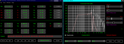
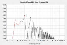
sorry, all i had pics of was the corner loaded sim... simple tapped pipe works great. (always)
ID = 54.10
Comment = NEW RECORD - NEW RECORD - NEW RECORD - NEW RECORD - NEW RECORD - NEW RECORD
|RADIATION, SOURCE AND MOUTH PARAMETER VALUES:
Ang = 0.5 x Pi
Eg = 66.00
Rg = 0.00
Fta = 0.00
|HORN PARAMETER VALUES:
S1 = 1000.00
S2 = 1000.00
Par = 20.00
F12 = 0.00
S2S = 1000.00
S3 = 1000.00
Par = 80.00
F23 = 0.00
S3S = 500.00
S4 = 500.00
Par = 80.00
F34 = 0.00
S4S = 500.00
S5 = 500.00
Par = 20.00
F45 = 0.00
|TRADITIONAL DRIVER PARAMETER VALUES:
Sd = 510.00
Bl = 27.87
Cms = 6.01E-05
Rms = 13.53
Mmd = 285.24
Le = 4.20
Re = 3.90
TH = 2P
|ADVANCED DRIVER PARAMETER VALUES FOR SEMI-INDUCTANCE MODEL:
Re' = 0.00
Leb = 0.00
Le = 0.00
Ke = 0.00
Rss = 0.00
|ADVANCED DRIVER PARAMETER VALUES FOR FREQUENCY-DEPENDENT DAMPING MODEL:
Rms = 0.00
Ams = 0.00
|PASSIVE RADIATOR PARAMETER VALUE:
Added Mass = 0.00
|CHAMBER PARAMETER VALUES:
Vrc = 0.00
Lrc = 0.00
Ap = 0.00
Lpt = 0.00
Vtc = 0.00
Atc = 0.00
Acoustic Path Length = 0.0
|MAXIMUM SPL PARAMETER VALUES:
Pamp = 100
Vamp = 25
Iamp = 4
Pmax = 1000
Xmax = 15.0
Maximum SPL Setting = 3
|ABSORBENT FILLING MATERIAL PARAMETER VALUES:
Fr1 = 63.00
Fr2 = 112.00
Fr3 = 9.00
Fr4 = 0.00
Tal1 = 100
Tal2 = 100
Tal3 = 100
Tal4 = 100
|ACTIVE BAND PASS FILTER PARAMETER VALUES:
High Pass Frequency = 0
High Pass Slope = 1
Low Pass Frequency = 0
Low Pass Slope = 1
Butterworth High Pass Order = 1
Butterworth Low Pass Order = 1
Linkwitz-Riley High Pass Order = 2
Linkwitz-Riley Low Pass Order = 2
Bessel High Pass Order = 1
Bessel Low Pass Order = 1
2nd Order High Pass Q = 0.5
2nd Order Low Pass Q = 0.5
4th Order High Pass Q = 0.5
4th Order Low Pass Q = 0.5
Active Filter Alignment = 1
Active Filter On / Off Switch = 1
|PASSIVE FILTER PARAMETER VALUES:
Series / Parallel 1 = S
Series / Parallel 2 = S
Series / Parallel 3 = S
Series / Parallel 4 = S
|EQUALISER FILTER PARAMETER VALUES:
Band 1 Frequency = 0
Band 1 Q Factor = 0.01
Band 1 Gain = 0.0
Band 1 Type = -1
Band 2 Frequency = 0
Band 2 Q Factor = 0.01
Band 2 Gain = 0.0
Band 2 Type = -1
Band 3 Frequency = 0
Band 3 Q Factor = 0.01
Band 3 Gain = 0.0
Band 3 Type = -1
Band 4 Frequency = 0
Band 4 Q Factor = 0.01
Band 4 Gain = 0.0
Band 4 Type = -1
Band 5 Frequency = 0
Band 5 Q Factor = 0.01
Band 5 Gain = 0.0
Band 5 Type = -1
Band 6 Frequency = 0
Band 6 Q Factor = 0.01
Band 6 Gain = 0.0
Band 6 Type = -1
|STATUS FLAGS:
Auto Path Flag = 1
Lossy Inductance Model Flag = 1
Semi-Inductance Model Flag = 0
Damping Model Flag = 0
Closed Mouth Flag = 0
Continuous Flag = 0
|OTHER SETTINGS:
Filter Type Index = 0
Filter Input Index = 0
Filter Output Index = 0
Filter Type = 1
MEH Configuration = 0
ME Amplifier Polarity Value = 1
Attachments
What’s that^^^?
Idk
I just saw it by accident on the web
Looks like 8 subs and 3 tops per side
I wonder what tops are those that you
Can splay them in groups of 3
OK did a same size, tuning TH my non standard way Vs your 1/4 WL with mine being for max efficiency and yours (relatively speaking) max BW.
I used your 66 V/2178 W power, but realistically they can only handle 1 kW without using a HP to make them ~ a one note boombox.
I used your 66 V/2178 W power, but realistically they can only handle 1 kW without using a HP to make them ~ a one note boombox.
Attachments
- Home
- Loudspeakers
- Subwoofers
- Dual Skar12 paraflex C CRAM