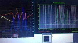
i do things a weird way …. But my impedance plot landmarks and sims are dead Nuts in high order qw enclosures unlike many peoples, typically ? I dunno why or what other people do, nor do I think I’m ‘right’. it’s dumb luck !!! 😝
Dats v3 versus horn response. I can’t complain, but I AM half retarded …🙃
Attachments
Last edited:

Is there an end correction in L45 in ‘PH1 mode?
in OD mode you find the offset driver position in a 300 cm qw pipe is ~105(104.72 if corner loaded and mass loaded/tapered) cm to fix the area of the 3/4 harmonic precisely.
in you add a 100 cm qw pipe to a 300cm pipe in PH1 mode it does it ‘perfectly‘.
is this similar/same type of thing?
in OD mode you find the offset driver position in a 300 cm qw pipe is ~105(104.72 if corner loaded and mass loaded/tapered) cm to fix the area of the 3/4 harmonic precisely.
in you add a 100 cm qw pipe to a 300cm pipe in PH1 mode it does it ‘perfectly‘.
is this similar/same type of thing?
In a transmission line, if we move the driver downstream to 0.33333 x (end correction) = ~ 0.349(???) it amazing 😀what happens
we kill the next harmonic by creating a helmholtz chamber (?) or exciting the pipe at V max for the 3x Fb freq(??) and the resonance peak/void is smoothed out perfectly until the next one at 5x, 7x, 9x…. Infinity…. Is it helmholtz or a qw mode ? I dunno, but it nulls out one of those resonances precisely if you look 👽
300cm
3/4 mode 104.72(100cm)
5/4 mode 62.83(60 cm)
7/4 mode 42.857142(44.88cm
man’s so on
but this same idea can be resolved by adding a resonatur instead (in parallel ) so they sun at 3:1 ‘in phase’ at exit which is velocity max for both of those freqs.
or 5:1,7:1… (but the 3/4 is still there or 3/4 and 5/4 )
yiu must fix/use the 3:1 essentially)
I dont understand why we would want to do anything else in ‘qw’, as the XO region and bandwidth are all ’fixed’ and ‘smooth’ if we look in simulation .
ultimately this is MORE important than anything? Or arguely so ?
It makes or breaks the BW and XO region. Anything else is kinda messed up(or worse) and is hard to incorporate with the ‘tops’ in PA or front stage in home/car ? And that matters a lot as soon as you’re ‘listening’ to these things in real reality instead of an spl/sim that forgets it?
i dunno?
Last edited:
when you got home!I haven't played with the PH1 function due to old HR version.
using the work machine is IT restricted
but once home.... Freeeeeddddoooommmmm!!! 😀
Dead link now in the archives: https://www.xlrtechs.com/dbkeele.co...Preprint) - LF Horn Design Using TS Paras.pdfT/S theory peters out at the driver's effective upper [Fhm], lower [Flc] mass corners, so any bandwidth response plot beyond these points are strictly due to [inputted] inductance [mH] and/or mass roll off, with on-line freeware generally just flatlining it:
Fhm = 2*Fs/Qts' end of acceleration BW
Flc = Fs*Qts'/2 end of roll off BW [normally never used]
Qts' = 2*Fs/Fhm
Maybe more easily understood from a horn loading POV along with all the extra math, pg. 7.
Sorry, in my haste I forgot to copy the header 


http://web.archive.org/web/20240415...Preprint) - LF Horn Design Using TS Paras.pdf
http://web.archive.org/web/20240415...Preprint) - LF Horn Design Using TS Paras.pdf

slow down on the meth old man! 🤣Nevermind (sorry) it was the phone, laptop works fine 👍🏼
- Home
- Loudspeakers
- Subwoofers
- Dual Skar12 paraflex C CRAM