Like this DAS sub?is a finite element analisys (Finite Element Method)
The 15FW4 15" loudspeaker used in the EVENT-115A has been engineered by DAS to provide outstanding performance and reliability. The 15FW4 speaker design has been optimized using Finite Element Analysis (FEA) and incorporates an extended 3? voice coil for high-efficiency and long excursion offering a power handling capacity of 1200W Program. Efficient cooling is assured thanks to the 15FW4's vented pole piece and abundant apertures in the speaker's back plate keeping power compression to a minimum while providing high acoustic output over extended periods.
So now FIR filters and FEA design is the trend for 2023
So worth the $$ or mostly the same except computerized with some new internal muffler 'twists' that look similar to some of the Paraflex 'bundle of pipes'?You have to ask? 😉
ok so i have the option of the BP1 modified PAL12 ( that only the Hornresp is done as of today)
or use the below Type C Skram design made for the DDX12


or use the below Type C Skram design made for the DDX12
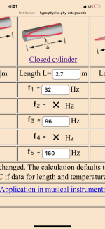
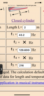
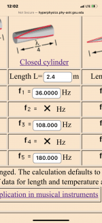
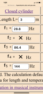
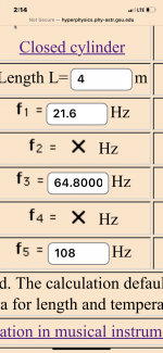
same thing essentially, but in a 'perfect' world and using PH1 mode to further describe the driver positions to which that ‘perfect’ is found
’perfect’ being no trace of the 3/4 harmonic and cancelation notch from the long sides 1/4 wave lengthfundamental
Last edited:
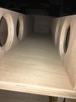
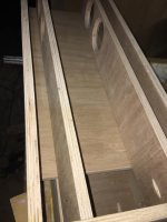
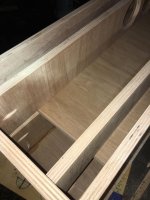
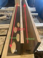
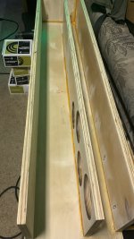
seems to work great… (here’s an actual example of a simple/built enclosure using different drivers) needs a big mouth once things get going !!👍🏼👍🏼I hate chuffing and port/exit noise …
Attachments
Last edited:
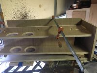
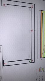
extended exit 'waveguide' option i ended up using on the coner loaded model that had DEEP smooth usable roll off to add (room gain) and diluted the brightness up top a bit
Last edited:
GM inspired ‘bundle of snakes’. 🔊🔊 or the square wave antena version of the b@se wave thingy ? Just folded onto itself, putting the exit at an odd harmonic velocity max(or however we could describe/illustrate this)
Attachments
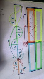

I dunno…. But lining 1/4 wave resonators up to each other, driving them at the ‘ ‘sweet spot‘ and exiting in the correct location sure is fun ! It’s all happy and sounds legit too. Impedance plot measures as simmed, etc.So worth the $$ or mostly the same except computerized with some new internal muffler 'twists' that look similar to some of the Paraflex 'bundle of pipes'?
keep it simple and it works?
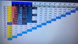
i got this with the 2 ddx cram type c at only 200 watts ( wich is great!!)
cause with 200w you get more than 130db output !!
only thing is that with more than 200w power you get more than 15mm excursion with the skars
hey guys so as MMJ showed on the plan i used the D2 version of the DDX and copied the HR parameters
but how do you wire the 2ohm coils ? in series so to have 4 ohms each driver and then in parallel ? as the HR says 2P ??
that means that one cabinet nominal ohms will be 2 ohms
so you will have 2 ohms or 8 ohms cabinets
depending if you wire the SKARS as series between Driver1 and Driver 2
so the each coil in the D2 will be wired in series for 4ohms total
and those 2 drivers in series for 8 ohm external load
so you can put 2 or 3 cabinets per amp channel
correct ?
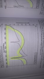
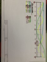
It worth compare the simulation using TH model vs Paraflex Model. The dip amplitude may look very different.
True! (Same drivers, same enclosure volume, apples to apples) and horn response remains accurate.
keep it simple and it works. Or Bend up a pretzel at random and …. Good luck🙈
(It seems approaching the 5/4 harmonic of the long side is always plagued with that shape in ‘parallel QW pipes‘. but misaligning them create that cliff, or the opposite . The left over parts of the resonance /cancel of the long side)
Attachments
Last edited:
True! (Same drivers, same enclosure volume, apples to apples) and horn response remains accurate.
I mean, the paraflex C model he found, MMJ was modeling using TH with open rear chamber, while you and me modeling it as PH1, so, worth maxoline compare the results, maybe one is more accurate then the other.
Thanks! Guess I'll skip it unless it ever shows up at the local used bookstore that historically sells such books at huge discounts.keep it simple and it works?
I do love the KISS system; it has served me and mine quite well! 🙂
oh, yes! very important detail and excellent to point out Marcelo. we can really polish up the paraflex ideas this way(and they get easier to build too). The Harmonics win every time, why fight it 🤓I mean, the paraflex C model he found, MMJ was modeling using TH with open rear chamber, while you and me modeling it as PH1, so, worth maxoline compare the results, maybe one is more accurate then the other.
Attachments
-
 39B092CB-32AF-4A1A-B18F-E990F60EA27D.png71.3 KB · Views: 74
 -
 39B9AA07-3AF1-44A9-BB32-57D7940C2777.png81.3 KB · Views: 62
 -
 40115600-9875-4E40-AEDA-C63A28639FAE.png76.2 KB · Views: 60
 -
 7F8A820B-88B6-4D65-AF73-EC68A231C839.png54.8 KB · Views: 61
 -
 28B3E946-9D87-4557-8008-7F7DDFD7F5B6.png60.6 KB · Views: 78
 -
 514E9867-ECA3-4BAF-BFF3-AD5BB9A291D8.jpeg210.4 KB · Views: 64
 -
 0A705BBA-723B-46BF-A344-6E33DA85FABA.jpeg75.4 KB · Views: 76
Last edited:
Coming of age audio wise from an era where efficiency wasn't just a performance goal, but THE goal, I'd want the highest impedance possible to keep current draw low as practical for HIFI/HT apps, hence lowest thermal power distortion, but due to all the advances in electronics, power supplies, driver power handling in recent decades, prosound nowadays apparently wants the speaker system to go straight to its heat sinking limits to maintain a ~uniform performance from the get-go and minimize the damage done by cycling through numerous heat/cooling swings*, so low impedance unless wanting to gang boxes together to get there, i.e. choose based on the needs of the app.correct ?
* Or as one local prosound engineer quipped, driver design is currently dictated by mobile audio requirements.
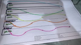
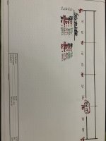
Parallel lives matter 😝🔊. Simple is best, once you look. Ignore those funny folds and shapes. this is important to understand and use. Reverse engineer it from here to fit in your ‘box’ shape needs, but this should be your ‘sim’ and for obvious reasons once you look (or build the simple version first to see(hear) and then compromise this as needed. Driver offset must be the same, csa must not get huge on the short side.. etc
explore this and see what happens otherwise. Make weird L and S entries to exploit any issues that horn response can point out very easily. Start here
explore this and see what happens otherwise. Make weird L and S entries to exploit any issues that horn response can point out very easily. Start here
Attachments
Last edited:
- Home
- Loudspeakers
- Subwoofers
- Dual Skar12 paraflex C CRAM