I was referring to The deliberate driver entry/tap position and it’s affect on the response. It’s independent of the driver choice.
Attachments
Last edited:

Below are the measured parameters of a conditioned Skar DDX 12 D2 thanks to Mr J.R. Vansickle and the Smith & Larson Woofertester 2 ..
NOTE: people can say what they want about Hornresp's Lossy Inductance tool not being accurate with a lot of drivers, and that is true, but in this case our subject is in the proper relative inductance range which allows the tool to be useful for improving the accuracy of our Hornresp model (when working with the DDX 12 driver)..... ...
To apply the Lossy Inductance tool click on "Le" in the Hornresp inputs screen while in edit mode until "Le" turns a red color.


Also keep in mind that by PA standards we can consider this driver to be a roughly 6 ohm nominal load when the coils are wired in series ..
To host a pair of these drivers in a high performance Compound QW/Horn loaded cabinet I suggest a Paraflex CRAM! approach such as one of the Paraflex Type "C" CRAM! 2x12 designs.
NOTE: people can say what they want about Hornresp's Lossy Inductance tool not being accurate with a lot of drivers, and that is true, but in this case our subject is in the proper relative inductance range which allows the tool to be useful for improving the accuracy of our Hornresp model (when working with the DDX 12 driver)..... ...
To apply the Lossy Inductance tool click on "Le" in the Hornresp inputs screen while in edit mode until "Le" turns a red color.
Also keep in mind that by PA standards we can consider this driver to be a roughly 6 ohm nominal load when the coils are wired in series ..
To host a pair of these drivers in a high performance Compound QW/Horn loaded cabinet I suggest a Paraflex CRAM! approach such as one of the Paraflex Type "C" CRAM! 2x12 designs.

Hey Brian, see post #45Modern car audio drivers with Qts < 0.40?
Hmm...
I'll believe that when actual measurements show that to be the case...
Thanks a lot Matthew.Also keep in mind that by PA standards we can consider this driver to be a roughly 6 ohm nominal load when the coils are wired in series.
You are referring to the dual 2ohm version of the DDX12 correct? As I can see the 1 ohm and 4 ohm values for parallel or series coil config.
So if you wire the driver in series you count it as 6 ohm nominal right? So paralleling 2 for a dual driver cabinet will give around 3 ohm load for the amp.
Last edited:
I will rerun the sims with Mathew provided breaked in driver parameters
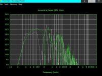
New Sim Using MMJ provided DDX12 numbers
for 4 cabinets @1kw per driver

OLD Sim with SKAR supplied numbers

for 4 cabinets @1kw per driver
OLD Sim with SKAR supplied numbers
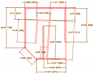
ok before going forward and start getting the actual dimensions of the box from the HR sim,
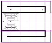
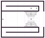
i need advice on how to tackle the dual driver inside the horn, BP1 made longer the baffle so to accommodate 2 drivers one in top of the other
as you can see on the right pic
but what about putting the drivers side to side just making the cabinet wider as you can see on the left pic
what aproach will be better ?
i mean freq wise as puting the drivers on top of each other maybe will make some nasty freq artifacts cause the top driver is almost next to the top
of the S2 path


i mean freq wise as puting the drivers on top of each other maybe will make some nasty freq artifacts cause the top driver is almost next to the top
of the S2 path

i need advice on how to tackle the dual driver inside the horn, BP1 made longer the baffle so to accommodate 2 drivers one in top of the other
as you can see on the right pic
but what about putting the drivers side to side just making the cabinet wider as you can see on the left pic
what aproach will be better ?
i mean freq wise as puting the drivers on top of each other maybe will make some nasty freq artifacts cause the top driver is almost next to the top
of the S2 path
i mean freq wise as puting the drivers on top of each other maybe will make some nasty freq artifacts cause the top driver is almost next to the top
of the S2 path
Last edited:
It's safer go side by side architecture.
going one on top of the other, each driver will be placed on a different offset, the total horn length is the same but the L12 for each driver is different.
For a subwoofer it might not be a problem.
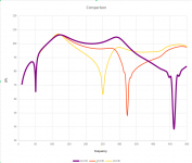
1) Simulate both side by side at lower position (shorter L12)
2) Simulate both side by side at upper position (longer L12)
3) Compare how the cancellation dip move, probably upper position is you worst case. Check the attached image for instance.
4) Calculate the distance between the drivers (upper - lower) check the equivalent frequency for the 1/4 wave length.
If you accept the frequency response with the driver at upper position and the equivalent frequency regarding driver position is outer of the bandwidth you want the loudspeaker to reproduce it will not be and issue for your case.
You can go deeper studding about acoustical coupling / cancellation regarding 2 driver and frequency reproduction.
going one on top of the other, each driver will be placed on a different offset, the total horn length is the same but the L12 for each driver is different.
For a subwoofer it might not be a problem.
1) Simulate both side by side at lower position (shorter L12)
2) Simulate both side by side at upper position (longer L12)
3) Compare how the cancellation dip move, probably upper position is you worst case. Check the attached image for instance.
4) Calculate the distance between the drivers (upper - lower) check the equivalent frequency for the 1/4 wave length.
If you accept the frequency response with the driver at upper position and the equivalent frequency regarding driver position is outer of the bandwidth you want the loudspeaker to reproduce it will not be and issue for your case.
You can go deeper studding about acoustical coupling / cancellation regarding 2 driver and frequency reproduction.
Attachments

Interesting to sim and observe
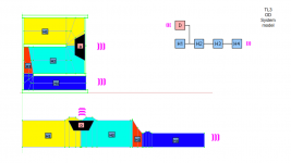
This model could be created with FreeCAD and released in the website if needed.
Booger, you may like the below model, it was released some weeks ago in the website, other then driver positioned at ~1/3 total length, you can control the CSA of the last segment to be equal or different from H1 and H2.
https://freeloudspeakerplan.rf.gd/pages/tl3.htm
Attachments
What book is that? Reads interesting!Interesting to sim and observe

- Home
- Loudspeakers
- Subwoofers
- Dual Skar12 paraflex C CRAM