Brian. if you check diaphragm displacement, you will see the excursion minima is indeed at 35hz (which would make this a 35hz tapped horn).
Yep, but the Danley TH118 has an excursion minimum at around 28 Hz and it shares the same box dimensions. That was the point I was trying to make.
the published impedance measurements do indeed indicate a 28ish excursion minima. interesttttting. strapping a 10 liter front chamber and increasing s3 (while decreasing s2) get the impedance chart more in line with what danley published, but not totally there.
If you fold it just like the drawing in the pic I showed in post 33 with S2 having NO path area except inside the cone it looks like you could gain an extra few inches (10?) by extending that top middle bend down further. And then if you put that lip on the back rounding the last corner that will do a bit of mass loading.
That should get you pretty close to your 28. The cab is right there in the pics. Sim it up and see what you get. I think I can find dimensioned drawings of this cab if you need them. If DSL did it you can do it. I'm pretty sure we know what drivers he uses in this cab I'm pretty sure I saw plans fully marked with dimensions at one point so...
That should get you pretty close to your 28. The cab is right there in the pics. Sim it up and see what you get. I think I can find dimensioned drawings of this cab if you need them. If DSL did it you can do it. I'm pretty sure we know what drivers he uses in this cab I'm pretty sure I saw plans fully marked with dimensions at one point so...
An externally hosted image should be here but it was not working when we last tested it.
Not sure how accurate this is, it's just a picture I found on the internet. Just add the baffle board to turn this from a 115 to a 118 (including the lip that mass loads the last bend like the pic in post 33), sim this up, and you should have the DSL TH118 measurements matching your sim.
EDIT - I don't know how to link that pic right. Scroll down in this thread and it's there, big and fully dimensioned - http://forum.speakerplans.com/plans-for-the-th115_topic14326.html#top
DOUBLE EDIT - I downloaded it and hosted it myself. Stupid imageshack. No time for your nonsense.
An externally hosted image should be here but it was not working when we last tested it.
Last edited:
Not sure how accurate this is, it's just a picture I found on the internet. Just add the baffle board to turn this from a 115 to a 118 (including the lip that mass loads the last bend like the pic in post 33), sim this up, and you should have the DSL TH118 measurements matching your sim.
Yup, I saw that. Thing is, that design has a faster expansion than my own (which should drive Fb up), and my own needs another 61 cm added to the length to achieve something like a 28 Hz Fb. That means that fold needs to exceed the path length of my own by at least 61cm (i.e. at least two feet).
That doesn't seem to be possible, given the differences the changes to the S1-S2 area might bring.
An externally hosted image should be here but it was not working when we last tested it.
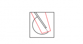
Here's what I see, and you can let me know where you think I'm wrong, because I see EASILY an extra 61 cm path length in the DSL version. (I didn't measure anything but at a glance it looks like an easy 61 cm difference.)
The red line follows the path of the DSL drawing, the purple line follows the path of your style of fold.
So in the DSL version, you already gain probably 10 - 15 inches by the time you get about 10 inches past S2, this part alone is a massive difference from your layout, I didn't mention this in the last posts because I thought it was exceedingly obvious. Then at the top middle of the box is the next huge difference (probably another 10 inch path length difference) for the same reason, because S2 goes right through the driver cone instead of taking up path length, which makes the bend at the top middle a lot longer too. The third big difference is the last corner where the stub provides a bit of mass loading, I wasn't sure how to draw that so I just made a jog in the line to add some path length which probably isn't too far off. So there's at least a couple more inches there.
Sim this as drawn and I'm pretty sure you'll find your 61 cm, if not more. So which part do you disagree with?
I see only three possibilities for this discrepancy.
1. My picture above is correct and the DSL path is at least 61 cm longer.
2. Danley's measured impedance is not correct.
3. Danley used magic or witchcraft to force a lower tuning.
#3 is clearly a bit sarcastic, #2 is fairly unlikely, and that leaves only 1 option IMO. He did it somehow and it's pretty clear to me that his path is a LOT longer than yours.
I didn't draw in the differences in the boxes themselves so if you like I can provide drawings of each box and their path length if this is not clear enough.
The red line follows the path of the DSL drawing, the purple line follows the path of your style of fold.
You're drawing a comparison between the DSL fold and the original SS15 fold, not the modified SS15 fold I was referring to in my last post. I need to find an additional 61cm to add on to the modified SS15 fold to match the DSL fold's ~28 Hz Fb.
Let's do a quick worked comparison between the original SS15 fold and an approximation to the DSL fold (which actually gives a line that's slightly longer) in a box that's the same size as the TH118. See diagrams attached. The first one gives a path length of 293.9 cm and the latter gives a path length of 317.6 cm. It's an increase of 23.7cm, but that's nowhere near enough to drop Fb to 28 Hz. Another 60cm needs to be found.
Now it's possible that the spreadsheet itself I used to model this is not calculating the path length properly. It uses an iterative process with the same formula so the risk of that is low, but I will check it over again this afternoon.
Attachments
Art achieved a lower tuning with the Keystone by using a mouth restriction.
I wonder what the mouth size on the TH118 is once the edge bracing and grille are taken in to account?
When accounting for the volume taken by the cone in the horn path note that there is flat area centered on the driver.
I wonder what the mouth size on the TH118 is once the edge bracing and grille are taken in to account?
When accounting for the volume taken by the cone in the horn path note that there is flat area centered on the driver.
Attachments


There's most of the difference right there. You didn't draw the "cone correction" section right and therefore you didn't go deep enough through the cone path and you drew the path with one bend through the cone instead of two. And you completely disregarded the mass loading stub in the last corner which adds either a bit of length or mass loading or both depending on how you want to describe it. Either way the sim doesn't care what it's called but it will make a difference.
I'm really curious though what theory you have as to why the tuning is 28 hz if the path length can't support that. I'm clearly showing it's a lot longer than you seem to think, but if you disagree how is it tuned where it is?
Last edited:
Also, are you simulating the cab in the plans I showed or is this just a wild guess? I'm guessing the latter since the "cone correction" and stub in the last bend in your drawing isn't even close to the DSL plans. You can't just take a wild guess at the dimensions and make pretty sizable errors and wonder why your sim doesn't match the measurements.
An externally hosted image should be here but it was not working when we last tested it.
There's most of the difference right there. You didn't draw the "cone correction" section right and therefore you didn't go deep enough through the cone path and you drew the path with one bend through the cone instead of two.
Your modification is a bit off because the truncated triangle isn't centered on the driver's cone (see attached diagram that shows the location of the driver), but in any case your modification may actually decrease the path length. The path length around a truncated triangle section should be less than the path length around the same triangle in its un-truncated form. In any case, the difference will be small. Remember, we're looking for 60 cm here. That's almost two feet of additional path length.
And you completely disregarded the mass loading stub in the last corner which adds either a bit of length or mass loading or both depending on how you want to describe it.
I believe the difference that it will make here is minor. Use the "enhanced centerline" method to draw the path around that stub, rather than those sharp angles. You should see any change it makes to the path length will be minor. Certainly not in region of 60 cm. Even if you use those sharp angles to define your path, the increase in path length is not going to be that significant.
I'm really curious though what theory you have as to why the tuning is 28 hz if the path length can't support that.
None yet 🙂. I have a theory that we might be analyzing the TH118 design incorrectly however. Instead of the standard S1-S5 layout with the driver at S2, instead perhaps it should be examined as a TH with a front chamber that fires into a horn that starts at that first section after the driver. I don't think that will shift Fb, but it does relax some of the design parameters a bit.
Attachments
Also, are you simulating the cab in the plans I showed or is this just a wild guess? I'm guessing the latter since the "cone correction" and stub in the last bend in your drawing isn't even close to the DSL plans. You can't just take a wild guess at the dimensions and make pretty sizable errors and wonder why your sim doesn't match the measurements.
It's a similar layout, not identical, in the same size cabinet. I don't believe there are going to be any major (i.e. 60cm) differences in path length between the two layouts.
I can't help but wonder if there is some 3rd dimensional folding on the baffle and this is the "magic" of the DSL designs like TH18. I mean Tom's LabSub is not just 2d and that is an old design... Like a fold within a fold, if you will. First saw this in Sine143's designs, but I am sure some guy patented it in the 1800's... 😀 IOW, create 2 paths within S12 of the XOC1/SS fold. So what appears to be cone correction or a restriction is actually part of fold.
Attachments
Hi Zwiller,
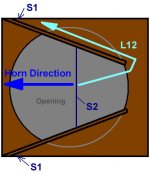
It is possible that L12 is longer than initially meets the eye (but I doubt it).
I remember djim talking about a folded around section in that area:
"Danley seems to use another approach. Some owners describe the Danley throats as having a "V" shape. Such "V" shape has two advantages:
1.) The "V" shape opening is closing towards the end of the driver probably to equalise the pressure.
2.) The second advantage of the "V" shape seems to be that the horn length from S1 to S2 is at least 3 times the diameter of the driver. By positioning the driver more away from S1, the pressure/loading differences between the two sides of the cone becomes smaller.
(The picture is meant as an example of the principle and is not a realistic representation of any Danley's TH's)" (end of quote)
And that is just one quote out of 100's of posts in the TH-18 Flat to 35hz! (xoc1's design) thread.
It could also be, that the TH118's impedance curve is impacted by the high power used for testing, and some form of low-cut filter. This might give the impression of a lower tuning than what is actual.
Regards,
Attachments
Oliver,
Forgot about that! Many thanks. Maybe someone here with more clout than I could mock something up and test and put it to bed. Seems simple enough to do a single fold design shootout one with a v throat and one without (and maybe even a Keystone for giggles). I also concur some of the Danley magic occurs at high power testing...
Forgot about that! Many thanks. Maybe someone here with more clout than I could mock something up and test and put it to bed. Seems simple enough to do a single fold design shootout one with a v throat and one without (and maybe even a Keystone for giggles). I also concur some of the Danley magic occurs at high power testing...
The "V-throat" approach looks like it might just do the trick (though it may also mean significantly reduced cross-sectional area at S1 and S2). I'll modify my spreadsheet tonight to consider that option to see what the calculated path length difference looks like.
I just thought of something else too - the volume of air between the cone and the baffle (in front of S2). For an 18" driver, that may be significant. I'm going to redo my HornResp sims to take that into consideration.
I think Danley does his measurements @28.3W, 10M. If Fb is shifting significantly downwards at that power level for a PA sub based around an 18" driver, I'd take that as a being a problem with the design, not a feature 🙂.
Your modification is a bit off because the truncated triangle isn't centered on the driver's cone (see attached diagram that shows the location of the driver), but in any case your modification may actually decrease the path length. The path length around a truncated triangle section should be less than the path length around the same triangle in its un-truncated form. In any case, the difference will be small. Remember, we're looking for 60 cm here. That's almost two feet of additional path length.
A little off topic here, but is that spreadsheet one that's available for anyone or does it cost something? I've not seen that one before.
Oliver, many thanks on the 100db 30Hz box! Starting to see just how big these bad boys gotta be to rock… Looks like you got a 1-2db edge on Crescendo’s six fold. Nice job. However, the 6 fold is a 34” cabinet, a bit easier build with 90deg angles, and as fate would have it, L12 (of first iteration) has no expansion is actually parallel which would make adding a v throat a snap if I dared to 😱
I would like to propose taking a step back and looking at the facts that are available to us instead of looking for magic or things that clearly are not there in the plans.
Here's the facts as I see them - picture 1 shows the TH115 and TH118 are exactly the same box with the TH118 having an extra baffle board and a bigger driver. As far as I know that is the only difference.
Fact 2 - the published tuning on the TH118 is around 27 hz while it's around 36 hz for the TH115, both shown below.
So if the only difference is the driver size and the extra baffle board I think we know exactly what is causing the difference - it really can't be anything else. And it makes sense, the TH118 has that stub at the last bend that constricts flow, which is mass loading and path lengthening. The extra baffle board reduces the size of the ENTIRE last segment. And the TH118 driver is a LOT bigger, just look at the pics of the cabs, the 18 inch driver fills up half the mouth hole while the 15 is just kind of tucked up out of the way not obstructing the mouth much.
So there's the stub in the last bend, the extra baffle board and the much larger driver ALL producing significant amounts of mass loading and lowering the tuning by a full 10 hz.
And as XRK pointed out there's also the grill rails around the mouth and the subs might have been measured with the grills in place too, which is ANOTHER significant amount of mass loading, but common to each of these models but not to the haphazard sims and estimations that have been done at this point to try to figure out the tuning.
I don't see any mystery here at all, frankly I'm shocked that anyone does. The TH115 is a 36 hz cab, the changes that make it a TH118 (namely a bit of path lengthening around the stub in the last bend and a whole lot of mass loading in three different areas) drop it to 26 hz.
But go ahead, be my guest, look for V shapes in the throat that clearly are not there in the plans and drawings, look for magic and imaginative solutions and completely ignore the facts staring you right in the face.
Just remember it was only a few years ago that people insisted that the simulators could not correctly predict tapped horn excursion. They insisted tapped horns were magic and did not obey the laws of physics. And I see this same type of discussion every time Danley's name is mentioned. I don't know why but people try to look a lot deeper than the surface facts, which is all that you really need.
If you sim the cab properly with the dimensions provided, and if the cab is built to those dimensions, the sims will match the measurements to a reasonable degree like they always do. Always.
Here's the facts as I see them - picture 1 shows the TH115 and TH118 are exactly the same box with the TH118 having an extra baffle board and a bigger driver. As far as I know that is the only difference.
Fact 2 - the published tuning on the TH118 is around 27 hz while it's around 36 hz for the TH115, both shown below.
An externally hosted image should be here but it was not working when we last tested it.
So if the only difference is the driver size and the extra baffle board I think we know exactly what is causing the difference - it really can't be anything else. And it makes sense, the TH118 has that stub at the last bend that constricts flow, which is mass loading and path lengthening. The extra baffle board reduces the size of the ENTIRE last segment. And the TH118 driver is a LOT bigger, just look at the pics of the cabs, the 18 inch driver fills up half the mouth hole while the 15 is just kind of tucked up out of the way not obstructing the mouth much.
So there's the stub in the last bend, the extra baffle board and the much larger driver ALL producing significant amounts of mass loading and lowering the tuning by a full 10 hz.
And as XRK pointed out there's also the grill rails around the mouth and the subs might have been measured with the grills in place too, which is ANOTHER significant amount of mass loading, but common to each of these models but not to the haphazard sims and estimations that have been done at this point to try to figure out the tuning.
I don't see any mystery here at all, frankly I'm shocked that anyone does. The TH115 is a 36 hz cab, the changes that make it a TH118 (namely a bit of path lengthening around the stub in the last bend and a whole lot of mass loading in three different areas) drop it to 26 hz.
But go ahead, be my guest, look for V shapes in the throat that clearly are not there in the plans and drawings, look for magic and imaginative solutions and completely ignore the facts staring you right in the face.
Just remember it was only a few years ago that people insisted that the simulators could not correctly predict tapped horn excursion. They insisted tapped horns were magic and did not obey the laws of physics. And I see this same type of discussion every time Danley's name is mentioned. I don't know why but people try to look a lot deeper than the surface facts, which is all that you really need.
If you sim the cab properly with the dimensions provided, and if the cab is built to those dimensions, the sims will match the measurements to a reasonable degree like they always do. Always.
- Status
- Not open for further replies.
- Home
- Loudspeakers
- Subwoofers
- Dual 18 Tapped Horn Design Concept