I wonder if a template of the front pannel for this board will be available?
Yes and no.
For sure I'll make available a document with the location of each element.
But I don't know yet if I'll have the boards populated.
A sole PCB is cheaper to ship, it's all TH so easy to assemble and you can customize your project by selecting specific parts.
A front panel template means you must use the same elements as I do. For example leds: they exist in various shapes and sizes, and what model you plan using is going to impact the front panel.
Or I can make a template for a specific list of components.
Let's discuss this further here.
Great idea - save all that point to point wiring.
Yes, of course the Mute switch on the encoder is wired on the PCB. So either you'd use this one, or you'd use a regular switch.
Looks good Ulf! Thanks for posting. Hope we also see the rear panel some day 😉
Rear panel....
Here we have 27' heat. But of course i have to make the photos!
It is not easy to bring the photos in the forum?!👋
Here we have 27' heat. But of course i have to make the photos!
It is not easy to bring the photos in the forum?!👋
Hi Nick,
the photos from inside with the Sjöström PSU and the rear panel are in the Galery.
Uploading does not work....
regards
Ulf
the photos from inside with the Sjöström PSU and the rear panel are in the Galery.
Uploading does not work....
regards
Ulf
OK, I have just tried to connect the board from a Windows 7 virtual computer in Parallels on OSX. The Leds are flashing as it tries to connect, but NUC complains that it can´t do it. Did anybody here manage to connect in this way?
I should perhaps mention that I did install the driver that came with NUC, and the device is shown in My Computer (on the Windows VM) as FT232R USB UART.
I have similar issue with NUC not connecting. Does your lcd turn on when you switch your unit on?
Are you using one of the new black pcb boards?
Are you using one of the new black pcb boards?
Never mind - board was in standby. 🙂 Hadn´t connected the display, so I forgot to check.. 🙂 Works now - at least it updated the firmware. 🙂
Hmm. it updated the firmware, but now it doesn´t register in the Windows environment at all.
Yes - its a black board.
I didn´t connect the display yet, as I have a VFD so I thought it wouldn´t do much anyway until I had configured the board to use it.
Yes - its a black board.
I didn´t connect the display yet, as I have a VFD so I thought it wouldn´t do much anyway until I had configured the board to use it.
Last edited:
Seems it could have been a power supply issue. At least it worked well once I changed to a switched power supply for the 5V. Thanks Nick for assisting!
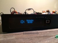
Here´s how the VFD looks behind 3mm acrylic. Now, it looks dirty because of the protection film, but I think it will look really nice once it´s off. 🙂

Here´s how the VFD looks behind 3mm acrylic. Now, it looks dirty because of the protection film, but I think it will look really nice once it´s off. 🙂
Attachments
Last edited:
That's a very tidy build F2a11. Looks like a mass-manufactured piece of kit, which is a compliment 🙂
Hello MellowFellow,
thank you for the compliment! The frontpanel is made by " frontplatten designer "
Schaeffer AG: Home in Germany. You make your design, they make the frontpanel.
It is not a mass- manufactured piece, you see my name on the panel. Inside i changed the couple elkos and the Opamps. It is not really necessary i think. The NAJDA ist a fine piece.
Thanks a lot for the compliment
Ulf
Linear Audio vol 4 cited before is definetely a must read
Sjostrom very nice build, also Check Super Regulator V2.2 - Power Supplies and Accessories - Circuit Boards
Sjostrom very nice build, also Check Super Regulator V2.2 - Power Supplies and Accessories - Circuit Boards
Display bug - fix posted in NUC V.1.1.2
I've been notified that there's a bug with the previous release.
This bug is related to the display routines and will show up if ... you have no display attached to the Najda.
If you have a display attached and the Najda is operating normally, then you can skip this update.
If you don't have a display attached and you have updated recently, then it might be that your Najda seems stalled. If this is the case, here's what you need to do:
- Attach a display or alternatively tie a 10 kOhm resistor between pin 14 (DB7) and pin 1 (DGND) on the display port. Now the Najda will start normally again.
- Download NUC V.1.1.2 and update the firmware to V.1.3.
- If that's fine for you, leave the resistor in place so that the micro doesn't wait for an event which is not likely to happen.
Sorry about this bug. It's related to supporting multiple display types (LCD, OLED, VFD and ... no display at all) and each configuration wants different GPIO settings.
In case of doubt, don't hesitate to contact me here or via email.
Nick
Hi Nick
What is the output impedance of Najda?
I want try to build a custom cable. RCA-> XLR with a resistor between RCA-ground and XLR-pin3
Thanks.
Bruno
What is the output impedance of Najda?
I want try to build a custom cable. RCA-> XLR with a resistor between RCA-ground and XLR-pin3
Thanks.
Bruno
Has anyone used a Squeezebox Touch as a front end to the Najda? I ask as I have just done so and I get clipping on the DSP output, switching to an Apple Mac seemed to reduce the problem, currently I have set the input 'gain' to -6db. Just how much effect would reducing the 'gain' to say -12db have on sound quality or does it not matter?
The Touch has EDO / TT3.0 mods applied, normally I run it into a Bushmaster without any problems when running single driver speakers.
Connection are Optical from Touch and Mac.
The Touch has EDO / TT3.0 mods applied, normally I run it into a Bushmaster without any problems when running single driver speakers.
Connection are Optical from Touch and Mac.
Last edited:
I use Pioneer N50 network player as front end to Najda (through coax input) . Also I get clipping on the DSP input, so I reduced input gain to -4 db, now it's ok.
Clipping in the digital domain in the input stream comes from 2 sources:
1. The signal already contains data at full scale - i.e., 0dB - and Najda is detecting this
2. Your media player is scaling the data by >0dB - i.e., it is applying gain
If you set Najda input to -1dB, then (1.) will never happen.
For (2.), check that media player's volume control is set to 100% or 0dB or OFF (whichever applies).
- Home
- Source & Line
- Digital Line Level
- DSP Xover project (part 2)