Very nice build thus far, congrats! 🙂
Re. your chassis and shield, your application is a bit particular given that you have symmetrical outs. I suppose you connect the XLR's GND to the chassis, right?
In any case, connection in one point between the panels is sufficient. I can't see what a "continuous connection" would bring in.
Re. your chassis and shield, your application is a bit particular given that you have symmetrical outs. I suppose you connect the XLR's GND to the chassis, right?
In any case, connection in one point between the panels is sufficient. I can't see what a "continuous connection" would bring in.
Thanks Nick,
I can post a pic, but I´m afraid it´s not much help. It´s just a regular chassis, but with anodized panels (anodized surfaces are not conductive). My question is: How important is continuity between each panel that touches, so that the "shield" is complete? Is it enough with one solid connection between each chassis part, or is it necessary with a "continuous connection" along the edges of each panel?
Anyway, here are a few photos of the build so far. I have yet to populate the S/E to BAL boards (detailed here), install power supplies properly, integrate the mux for multiple SPDIF inputs etc. Moving very slowly, as I have a working nanoDigi setup right now, and I want to get everything right.
The display on the right shows the led status pins - it works fine with polling, but I agree with you that interrupts are more proper. Using multiple pins with interrupts on the Arduino requires a bit more effort on the coding side, so I´ll see if it´s necessary to do so. However, I don´t think it will be a problem that the LEDs won´t show exactly the Arduino is processing something else, as the Arduino won´t process anything that takes more than a a split second anyway - but we´ll see.
Very nice build thus far, congrats! 🙂
Re. your chassis and shield, your application is a bit particular given that you have symmetrical outs. I suppose you connect the XLR's GND to the chassis, right?
In any case, connection in one point between the panels is sufficient. I can't see what a "continuous connection" would bring in.
Yes, I will the AES-48 standard. Pin1 and the shield will be shorted and connected to the chassis. This is done on the SE/BAL boards, making a "shield plane" (separate from the gnd plane) on these boards part of the chassis.
Thanks for the nice comments btw. 🙂
BTW: Can you explain how the remote bit works? It shorts when the Najda is booted right - but when i measure the "short" with a multimeter, there seem to be something there that confuses the multimeter - it reads about 600 instead of 0 and a beep. Is it safe to connect an arduino input pin to one side, GND to the other, using internal pullups to the input pin HIGH until the remote is shorted, which should pull it LOW?

That´s a nice enclosure.may I ask what the price is?Hello, Najda fans!
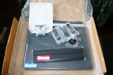
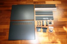
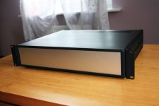
Today I've got my enclousure from Takachi, Japan. Very good made and easy to assemble. Still waiting for the other parts.
And shipping cost? 🙂
Hi Ryssen!That´s a nice enclosure.may I ask what the price is?
And shipping cost? 🙂
The enclosure is MSR88-43-35BS
http://www.takachi-enclosure.com/data/c1213/c_en_p165-169.pdf
The price is $101.64 USD and freight charge EMS (express) was $108.00 to my address.
Hi Nick,
any news on the expansion board?
Uwe
Hi Uwe,
The expansion board is now with the PCB manufacturer (as well as the front board we discussed earlier). Next step is SMD assembly, then test then release 😉
BTW: Can you explain how the remote bit works? It shorts when the Najda is booted right - but when i measure the "short" with a multimeter, there seem to be something there that confuses the multimeter - it reads about 600 instead of 0 and a beep. Is it safe to connect an arduino input pin to one side, GND to the other, using internal pullups to the input pin HIGH until the remote is shorted, which should pull it LOW?
Hi Martin,
Please check this previous post, it should contain all the info you're looking for.
Nick
Since you like pictures Nick, I will post another. 🙂
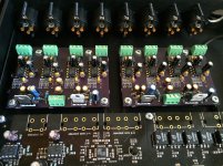
I have populated the BAL/SE boards (almost - I forgot to order the input connectors.. )
Anyhow - at least it looks nice. I think the design is solid, so if these don´t work it´s probably because I made a mistake in soldering or ordered the wrong parts. Lets see how it goes when I power them up.
Which brings me to this:
1. POWER
These boards are powered by +/- 12V, just like the Najda, and with LM337/317 regulators to bring the voltage to +/-9 V.
I´m taking my time with this build, and would rather not feel like I could have done better on the power supply side. On the other hand, I don´t want to throw money out the window if it doesn´t provide audible benefits.
I know you recommend switched supplies - so here are some questions:
Are there any audible or measurable differences on the Najda outputs when using different power supplies? I aim to play with high efficiency speakers at some point (this is one of the reasons I wanted the CS3318 in my setup).
I already have two 12V Meanwell supplies that work with zero load. Is there any reason I shouldn´t just get another 5V supply and use these three together? In this case, each would be regulated independently, but each can be adjusted. I will build it as class ii btw, so the ground would not be referenced to safety ground, so I figured I could just reference one of the 12V supplies "backwards" to get -12V from the common gnd.
My hope is that you will say "go switched", any noise from the PSU will be removed by caps/regulators, and you won´t hear any residual, and sure, get the 5V supply. 🙂
IF you say: Go linear if you want to squeeze out the last bit of performance - is there anything I should avoid? I read somewhere that shunting power supplies are not ideal when used with downstream smoothing caps and regulators (can´t remember where). Is there a linear solution that is as simple as getting a +5,+/-12V switched mode supply, or does it entail getting separate bits (trafos) etc.
Or - is the best combo switched mode (say 6V and +/-15V) and then some regulation to 5V and +/-12V.
Apologies if this has been answered already - again, it´s a long thread and difficult to search for terms this generic.
2. REMOTE (again)
Thanks for the reply above Nick! Let´s say I have a power amp in a separate enclosure, and the connections between the Najda and the amp follow the AES-48 convention. Would I introduce any ground loop by running a pair of wires from the remote connector to the power amp, or will the isolation ensure that this won´t happen? I know that the standby pin on the Hypex SMPSs are also optocoupled - but I suppose that wouldn´t even be necessary since the Najda´s remote connector is already isolated, right? EDIT: Just realised that doens´t make any sense - both terminals would be required for one signal (say a 12V signal), and it would therefore be necessary to run a separate ground wire too I suppose - which won´t be isolated). Let´s rephrase: Given separate amp/najda enclosures, how would I ensure no ground hum by using the remote connector to wake up the amps?
Attachments
Last edited:
Since you like pictures Nick, I will post another. 🙂
That's correct Martin, I like pictures. 🙂 Who doesn't? 😛
I know you recommend switched supplies [...]
I do recommend switched supplies indeed because they're available off the shelf with all the required power lines. In other terms, I recommend these supplies for simplicity and ease of use, and because they're compact and efficient.
If you should go linear or switched, I think this is your take. I suppose half of the users will say that a linear supply is better and the other half will tell that a switched one is good enough - and everybody is actually right because we don't want to start yet a new debate on switched vs linear PSUs, do we? 🙂
2. REMOTE (again)
Given separate amp/najda enclosures, how would I ensure no ground hum by using the remote connector to wake up the amps?
The relay command is isolated: there's no current flowing between the Najda and the external gear. It seems to me that you're confused about how that works. Please see the circuit diagrams in the optocoupler datasheet, as well as the application example in the StartUp guide.
Yes - no need to start a debate here 🙂 But are there any measurements so I can do a at least somewhat informed decision?
OK - will do more self study on the trigger 🙂
OK - will do more self study on the trigger 🙂
Regarding those linear supplies, any tips on more cost efficient regulators? I know about the SSR01/SSR02 superregs but at 3x900SEK they're not among the cheapest. What other alternatives are there? Preferably kits or prebuilt.
The expansion board is now with the PCB manufacturer (as well as the front board we discussed earlier). Next step is SMD assembly, then test then release 😉
Nick
Hi Nick!
I wonder if the release date of the front board is exist? When it will be available for the order? Is preorders are possible?
Regards, Mike
Hi Mike,
Yes I confirm the front board and the expansion will be available early July.
No need to pre-order: I set aside one front board for you.
Nick
Yes I confirm the front board and the expansion will be available early July.
No need to pre-order: I set aside one front board for you.
Nick
Hi Mike,
I set aside one front board for you.
Nick
Thank you, Nick!
Hi Mike,
Yes I confirm the front board and the expansion will be available early July.
No need to pre-order: I set aside one front board for you.
Nick
Do you have any prices for them?
No I don't have definitive pricing info yet, it's coming soon.
For the front board, I'm leaning towards 2 options:
Option 1: the PCB alone. Then you need to source your own parts. The advantage with this option is that shipping costs will be low (letter format).
Option 2: the PCB + all the parts, which are:
- Push-buttons + black caps
- OLED display (white text on black background)
- IR sensor
- Rotary encoder with central push-button, the required discrete resistors and capacitors, and a black aluminum knob
- Leds
- All cables (length 20 cm)
Option 2 will not fit in a letter format, so shipping costs will be higher.
Nick
I'd like to sign up for one of those front panels once the price becomes available! As a temporary solution, at least.
Hi Bjorn,
No problem, I reserve one front board for you. I doubt it's going to be a temporary solution though 😉
Pricing info will be available this week.
Cheers
Nick
No problem, I reserve one front board for you. I doubt it's going to be a temporary solution though 😉
Pricing info will be available this week.
Cheers
Nick
- Home
- Source & Line
- Digital Line Level
- DSP Xover project (part 2)