Howdy,
I'm planning a project for this summer using Ripole method. The goal is to build stereo basses, not subwoofers. I found this driver, what do you guys think about it.
Visaton WS 20 E 8
http://www.visaton.com/en/chassis_zubehoer/tiefton/ws20e_8.html
8"
SPL: 88dB 1W/1m
Xmax: 12mm
Fs: 47Hz
Qts: 1,23
Vas: 44l
Using 4 per side, total 8. Aim is to cover 30ish Hz - 200Hz range.
For 22€/piece.
For starters I'll be mating them with Fostex FE206E in a baffle with highpass around 200Hz.
--
Tuomas
That Visaton WS 20 E 8 has Xmax 3mm and not 12mm. Height of the voice coil is 11mm and gap height is 5. So Xmax will be (11-5)/2=3mm or +/-3mm.
If you wish to use 8" Visaton drivers then better pick up TIW 200 XS 8 OHM http://www.visaton.com/en/chassis_zubehoer/tiefton/tiw200xs_8.html It has true Xmax 11mm (+/-11mm).
If you wish to use 8" Visaton drivers then better pick up TIW 200 XS 8 OHM http://www.visaton.com/en/chassis_zubehoer/tiefton/tiw200xs_8.html It has true Xmax 11mm (+/-11mm).
Ah, my bad. Thank you for correcting.
Any driver goes that I can get from Europe cheap. I'm trying to squeeze this project in a really tight budget, at the price of one "TIW 200" I get 5 "WS 20".
One thing to consider too is Qts of the drivers, am I right? Is Qts >1.00 right way to go if I don't want to use any EQ? (From the graph above that Rudolf provided)
--
Tuomas
Hi,
have a look at www.Intertechnik.de
Their Gradient brand lists some nice budget drivers, eg. the GPC-188
use 6 or 8 per side, or the GPC-226 use 4-8 per side.
Very similar are the W180 and W220.
They are very similar to the former Westra drivers, which have proven to work well in a dipole if used in miultiples. See my ESEL-project
jauu
Calvin
Rudolf said:Making the front and rear loads symmetrical looks like a good idea, but what about making the front and rear excursion from the idle position symmetrical? The second looks like an even better idea, but does not imply the first automatically IMHO. [/B]
I am still trying to figure out how to measure the excursions without using of Klippel tool.
And it's not clear if symmetrical excursions of the driver in RiPol design will lead to symmetrical changes in SPL at ports of the sub.
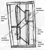
I have got some new idea about my version of W/Ripol. The idea is to trap exhaust from the pole vents into dedicated sealed eclosures. This construction will allow usage of somewhat noisier drivers.
Enclosures can be also used to house electronics. I am planing to mount the O Audio BASH 500W plate amp on the left side of the cabinet into bottom sealed enclosure.
In addition to that, reduction in radiating area of speaker drivers from the back side will make the sub radiation pattern somewhat more like cardoid.
Attachments
Rudolf, Calvin,
What do you guys think of my proposed design? Are there any hidden issues? Will I have problem with voice coil overheating? Those sealed enclosures will be about 17 liters. And the woofers are 18" Russian Pro woofers with 4" voice coils.
Thanks in advance.
What do you guys think of my proposed design? Are there any hidden issues? Will I have problem with voice coil overheating? Those sealed enclosures will be about 17 liters. And the woofers are 18" Russian Pro woofers with 4" voice coils.
Thanks in advance.
Iliya,
there might be some hidden issues. But since nobody has tried your proposal yet, we don´t know how big those issues could be. Foremost I would see the area in the middle between the two drivers as a risk. There will be a high pressure gradient in that area, with forces that are far off the drivers design axis.
Dipoles typically don´t have issues with voice coil overheating first, but with the excursion limit!
Thank you for your suggestions Rudolf. To tell you the truth I do not see that high pressure in between driver cones concern as a big issue. Let me explain why:
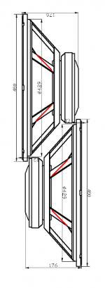
First of all the cones are much smaller than the driver frames. Please see the attached picture where I draw additional red lines as continuation for black lines that already were there on the original drawing showing the cone. I think that's where the cone is. See, that magnet is 220mm in diameter and the voice coil is 100mm.
The second thing is that cones are round and shown black/red lines are only the contour lines, and rest of cone surfaces will be even further away from each other.
But I am concerned about voice coil temperature because in my latest revision pole vents will be exhausting into fairly small sealed chambers. In this case the heat may be accumulating there over time.
Attachments
Small point
Why isnt it pushpull design, which would be the obvious choise ?
Im not sure, but if theres significant noise from voicecoil, which is what you are trying to solve by closed chamber behind magnet, I would expect the noise to make its way forward through the dustcap, as well, maybe even "amplified"
Also the small closed chamber will have a ressonanse, using the magnet venting as a amplifying tube, playing through the dustcap
Just a homebrew theory 🙄
Question re: Q>1.00
Hi there: In ost #163, tpakkanen asks if Q >1.00 is the way to go and woofer Visaton Ws20E-8 inch was descussed. The trade off would be a woofer with a Qts= 1.23 and a Xmax of 3mm (on VC/magnatic gap) however, (with a 12mm mechanical maximum) vers a diferent Visaton woofer with a Qts less than half of that, with a Xmax of 12mm? reference the paper written by Dick Pierce (last paragraph) posted in Volvotreater's home page, then go
to downloads what-is Q
.....regards, Michael
tinitus said:Small point
Why isnt it pushpull design, which would be the obvious choise ?
Im not sure, but if theres significant noise from voicecoil, which is what you are trying to solve by closed chamber behind magnet, I would expect the noise to make its way forward through the dustcap, as well, maybe even "amplified"
Also the small closed chamber will have a ressonanse, using the magnet venting as a amplifying tube, playing through the dustcap
Just a homebrew theory 🙄
There are two reasons why it's not a push-pull:
1. The push-pull design as proposed by Linkwitz is supposed to suppress even order harmonics. And I am not so sure that it's particularly good thing to do. As I read just recently the level of second harmonic might be much higher than level of third harmonic before becomes detectable by listeners. And I am concerned that if we reduce the level of even order harmonics then odd order harmonics will become prevalent in the harmonics spectrum and sound will be less pleasurable. In addition to that I would like to mention that as far as I know the most of tube amps have even harmonics higher than odd ones and that seems to be the major reason for so called "tube sound" that many people like so much.
2. The second reason is the size of the speaker cabinet. My goal was to make is as compact as possible.
Regarding the noise from the vents and closed chambers:
I do not know yet for sure how noisy those particular drivers are. I just have been told on a forum that there is some noise from the vent and lead wires. I will get my drivers in about two weeks and check them out. However from this thread, Linkwitz research and other sources I understood that the major reason why many drivers will not suite for a dipole is a wind nose from their pole vents. So I thought that if we trap that noise into closed chambers that BTW should be filled with a sound absorbing material like synthetic wool then we can solve that noise problem. And in addition to that as I already mentioned above there is one positive side effect of reduced sound radiation to a rear. However I am not insisting on having closed chambers. They can be also open to the rear or variovented to the rear as well. The later might be in fact the best solution as it will allow the coils ventilation, noise reduction, will reduce a box resonance and will still provide a guarded space for the amplifier at the same time. That’s killing not just two but four birds with a same stone. 🙂
Since its a sub, ANY kind of reduced distortion would be welcome
The considerations you have about distortion relations would only be an issue further up in frequency
The closed magnet chamber
I will suggest you do the chamber, but make it open, so that it can breathe freely
Just heavily stuffed
The considerations you have about distortion relations would only be an issue further up in frequency
The closed magnet chamber
I will suggest you do the chamber, but make it open, so that it can breathe freely
Just heavily stuffed
verticle stacked ripoles
Hi there: Using the two OB units shown in post #160, stacked verticle to make an enclosure approximately 29-inches high x 13-inches wide x 9-inches deep (for a 10-inch driver, 6-inches deep). Would the ripole summation of exit waves be acceptable? Also assuming a Qts >1.0 <1.2 as recommended (M.King, D. Pierse), as referenced posts above (#163 & #171). ....regards, Michael
Hi there: Using the two OB units shown in post #160, stacked verticle to make an enclosure approximately 29-inches high x 13-inches wide x 9-inches deep (for a 10-inch driver, 6-inches deep). Would the ripole summation of exit waves be acceptable? Also assuming a Qts >1.0 <1.2 as recommended (M.King, D. Pierse), as referenced posts above (#163 & #171). ....regards, Michael
Re: verticle stacked ripoles
What picture are you referring to? There two of them. The bottom one is mine the top one is from this website: http://www.lautsprechershop.de/hifi/index_en.htm?/hifi/ripol_en.htm.
I don't quite understand what you mean by "ripole summation". If you are concerned that my proposed design has two front outputs rather then one I think that it should not matter as front output slots are located within one foot from each other and the wave length even at 80Hz is more than 14'. So the phase shift between those two front outputs will be very minimal.
Regarding the drivers Qts: if you are using active filtering and separate sub amplifier then I think that the lower Q is better. But if you are building a passive dipole sub then you would need drivers with higher Q. However I think that Q > 0.7 for the RiPole would not be desirable as this design also raises the Q of installed drivers.
BTW I would strongly recommend you to read this discussion: http://www.audiocircle.com/circles/index.php?topic=54844.0
P.S. Michael would you please write your questions in some more detailed fashion. Sometimes it’s hard for me to understand what exactly your question has been about.
j.michael droke said:Hi there: Using the two OB units shown in post #160, stacked verticle to make an enclosure approximately 29-inches high x 13-inches wide x 9-inches deep (for a 10-inch driver, 6-inches deep). Would the ripole summation of exit waves be acceptable? Also assuming a Qts >1.0 <1.2 as recommended (M.King, D. Pierse), as referenced posts above (#163 & #171). ....regards, Michael
What picture are you referring to? There two of them. The bottom one is mine the top one is from this website: http://www.lautsprechershop.de/hifi/index_en.htm?/hifi/ripol_en.htm.
I don't quite understand what you mean by "ripole summation". If you are concerned that my proposed design has two front outputs rather then one I think that it should not matter as front output slots are located within one foot from each other and the wave length even at 80Hz is more than 14'. So the phase shift between those two front outputs will be very minimal.
Regarding the drivers Qts: if you are using active filtering and separate sub amplifier then I think that the lower Q is better. But if you are building a passive dipole sub then you would need drivers with higher Q. However I think that Q > 0.7 for the RiPole would not be desirable as this design also raises the Q of installed drivers.
BTW I would strongly recommend you to read this discussion: http://www.audiocircle.com/circles/index.php?topic=54844.0
P.S. Michael would you please write your questions in some more detailed fashion. Sometimes it’s hard for me to understand what exactly your question has been about.
verticle stacked ripoles
Hi there Iliya: Many thanks for the reply and the two web references. Between these, you have provided to me a better understanding of the ripole design. Inspite of the roundabout way of asking a question, you answered my main concern about the acceptable driver Qts usable in the ripole design. My verticle stacking thought was based on the concept of reducing the depth of the units by making two units with the slots short side over each other. I have no question or concern about your design and inderstand the acoustic outputs of the two slots in you design will sum with out cancelation as you pointed out in your reply. again thanks for the informative reply, ... regards Michael
Hi there Iliya: Many thanks for the reply and the two web references. Between these, you have provided to me a better understanding of the ripole design. Inspite of the roundabout way of asking a question, you answered my main concern about the acceptable driver Qts usable in the ripole design. My verticle stacking thought was based on the concept of reducing the depth of the units by making two units with the slots short side over each other. I have no question or concern about your design and inderstand the acoustic outputs of the two slots in you design will sum with out cancelation as you pointed out in your reply. again thanks for the informative reply, ... regards Michael
[B]tinitus[/B] said:The closed magnet chamber
I will suggest you do the chamber, but make it open, so that it can breathe freely
Just heavily stuffed
What if I make it closed but use one or two Flow Resistance Vents also known as Variovents per enclosure. Vents can be located next to magnets so the exhaust from them goes into center chamber that is open to rear. Any thoughts?
tpakkanen said:Howdy,
I'm planning a project for this summer using Ripole method. The goal is to build stereo basses, not subwoofers. I found this driver, what do you guys think about it.
Visaton WS 20 E 8
For starters I'll be mating them with Fostex FE206E in a baffle with highpass around 200Hz.
--
Tuomas
Hi Tuomas,
I have similar goals to yours (i.e. 200hz upper freq), but I'm going with a single 12" per side (actively equalized).
In this range, the peerless sls-315 driver is cheap and seem to be very reliable. The only thing that bothers me is the high Le and rather small voice coil.
An alternative is looking into Beyma woofers, the 12BR70 and SM112/N being cheap and probably better than the Peerless.
My main issue is wall proximity (40-70cm max from backwall and one of the side walls is also at roughly 70cm).
Second main issue is the baffle dimension: no more than 36cm, small and good looking (WAF)
I have been suggested side-firing woofers (U-frame), closed box (no thanks) and then I found the ripoles. Also 90° rotated with woofer open or closed would make sense.
The "N" shape with single driver seems the most suitable for small baffles. And Ridtahler puts them close to walls, which solves my problem n.1.
Re: Re: verticle stacked ripoles
Because audiocircle database failed just a few days ago, the link does not work anymore. Which was the forum and topic title?
Iliya said:BTW I would strongly recommend you to read this discussion: http://www.audiocircle.com/circles/index.php?topic=54844.0
Because audiocircle database failed just a few days ago, the link does not work anymore. Which was the forum and topic title?
Re: Re: Re: verticle stacked ripoles
I wish I remember. It was a description of work in progress on one simmetrical RiPole with two 15" Beyma drivers. Sub was placed by a couch. First it was without side walls. Then with small side walls then with full size side walls. Then center chamber was filled with bunch of MDF plates with U-shaped cut for drivers and exhaust to front side. That change lifted low end output by whole 3dB.
Telstar said:
Because audiocircle database failed just a few days ago, the link does not work anymore. Which was the forum and topic title?
I wish I remember. It was a description of work in progress on one simmetrical RiPole with two 15" Beyma drivers. Sub was placed by a couch. First it was without side walls. Then with small side walls then with full size side walls. Then center chamber was filled with bunch of MDF plates with U-shaped cut for drivers and exhaust to front side. That change lifted low end output by whole 3dB.
- Home
- Loudspeakers
- Subwoofers
- Drivers / parameters for ripole subs