Finally done ! I received the last ribbon cable that I was waiting on and managed to hook everything up and give it a short test last night in my garage workshop system. My first impressions are very favorable, very clean and clear, low noise with big sound stage. Tonight I'll hook it up to a decent system and burn it in for a while and give it a hard listen. I'll be swapping out an Aikido pre to do a comparison on my F6 amp feeding a pair of Jordan JX92s back horns which is a pretty revealing combo.
Paul
Paul
Ok, burned it in for only a few hours and gave it a hard listen last night. Love the convenience of all of the controls, especially the balance control, and the multiple inputs. Very practical preamp. The tone controls were fun to play with, but I didn't really need them in my room. Really impressive imaging, wide, layered sound stage. Very precise, neutral sound. It didn't kill my Aikido however, the two preamps did sounded different, the Self pre seemed a little dryer than the Aikido. The Aikido seemed a little (very little) blacker in the background and the note decays seemed more sustained. I did play with the tone controls to try and match the Aikido and came close to the tonality. The self pre is certainly a great sounding more flexible piece of gear. I'm leaving it in for a while to let it settle and get used to it.
Good evening,
Yesterday I have received remaining capacitors, and completed soldering pre-amplifier.
All work as a charm, no issues at powering, left burning over night.
Listening at the moment, impressive, wide stage, and a lot of options to adjust the sound you would like.
Need to start thinking about enclosure for it.
Thank you Carl and Doug Self for designing and arranging everything.
Best regards.
Sasha.
Attachments
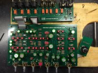
I almost forgot, thanks Doug, I got my PCB's!
I just noticed (before posting) that my PCB version is a V1.2 instead of a V1.2d. Out of curiosity, what are the differences?
I just noticed (before posting) that my PCB version is a V1.2 instead of a V1.2d. Out of curiosity, what are the differences?
I almost forgot, thanks Doug, I got my PCB's!
I just noticed (before posting) that my PCB version is a V1.2 instead of a V1.2d. Out of curiosity, what are the differences?
Versioning is all under my control. There have been 3 versions of the main board. The earliest version had two extra resistors per channel that were deemed to be not needed. Later versions improved the board layout for ease of assembly and aesthetics. However overall performance and parts used are identical across all versions.
Last edited:
sockets for the op-amps
Hello All,
I notice in the photos that some builders are using sockets for the op-amps. What is the object of the sockets? Is there a thought of rolling in another part?
DT
Hello All,
I notice in the photos that some builders are using sockets for the op-amps. What is the object of the sockets? Is there a thought of rolling in another part?
DT
Hi, all. Quick questions about the ribbon cables.
Thanks
Mo
- Is it typical to buy regular flat, 20-conductor ribbon cable and fold it over, or is there actually 20-conductor 2-row cable?
- When I buy the header assemblies (Mouser 571-103308-5), do they come with the corresponding female connectors or is there a separate part number I need to order? If so, could you recommend one that will fit?
- The I/O BOM calls for 3 headers and the Pre-Amp BOM calls for 2, for a total of 5. Should that be a total of 4, not 5?
Thanks
Mo
Hi, all. Quick questions about the ribbon cables.
- Is it typical to buy regular flat, 20-conductor ribbon cable and fold it over, or is there actually 20-conductor 2-row cable?
- When I buy the header assemblies (Mouser 571-103308-5), do they come with the corresponding female connectors or is there a separate part number I need to order? If so, could you recommend one that will fit?
- The I/O BOM calls for 3 headers and the Pre-Amp BOM calls for 2, for a total of 5. Should that be a total of 4, not 5?
Thanks
Mo
Harold
the cable is flat and does not need to be folded over.
the header assemblies do not come with the female connectors. i think you would need 517-89120-0101 or 517-8920. i am not sure what the difference is between them
the correct number of headers is 4 if you are using the revised I/O board and 2 if your are using the original. the preamp bom included parts for the
original I/O board. if you are using the revised I/O board mke sure you have the right number of relays (9)

the cable is flat and does not need to be folded over.
the header assemblies do not come with the female connectors. i think you would need 517-89120-0101 or 517-8920. i am not sure what the difference is between them
EDIT: Ah, I see from looking at the diagram of the female connector you recommended that these connectors automatically transition the 1 row by 20 cable into 2 rows by 10. Thanks.
As another Canadian, where do you source components besides the usual suspects, Mouser and Digikey? (I'm finding some parts on the BOM that are out of stock and will require two orders...with the often exorbitant shipping costs we Canadians face.)
Last edited:
As another Canadian, where do you source components besides the usual suspects, Mouser and Digikey? (I'm finding some parts on the BOM that are out of stock and will require two orders...with the often exorbitant shipping costs we Canadians face.)[/QUOTE]
i also mainly use mouser/digi. there are a couple of local suppliers that i can get generic resisters capacitors etc, but anything beyond that and they are not much help. i am in burlington ont and Parts Connexion is also located here. i have placed orders for pickup and avvoided shipping.
the company i work for has an office in buffalo so i can get stuff shipped there in a pinch.
big problem these days of course is the canadian dollar!!
The latest BOMs
Hi, all, If you are looking for the most recent BOMs for the pre-amp, power supply and enhanced I/O boards, please refer to the first post in this thread and to Carl's own I/O BOM.
Well I'm sure it is well intentioned, the archive kindly supplied by jan.didden does not include the latest BOMs. (EDIT: More specifically, the part quantities in the Pre-Amp BOM aren't correct.)
Last edited:
i got the ribbon cables today and powered up the unit. sounds great, but i have a hum/buzz. it is not there with zero volume and quite loud at full volume. it gets noticeably worse if i touch the ribbon cable connecting the main board to the IO board.
also, the heat sinks on the power supply seem to run very warm. they seemed to max out at about 55C. is this normal?

also, the heat sinks on the power supply seem to run very warm. they seemed to max out at about 55C. is this normal?
Troubleshooting Your Preamplifier
mik000000,
Have you found your problem? Your preamplifier should be stone quiet. The only time you might hear noise would be when you are switched to an unterminated input. The power supply runs warm but not as warm as what you are reporting. The added temp suggest that your preamp is pulling more current than it should. I suggest that you check your solder joints with a magnifying lense. It sounds to me that you have a solder bridge somewhere. A good place to start would be the connectors under the ribbon cable. Also check the ribbon cable itself. Sometimes those end connectors are not swedged as well as they look.
i got the ribbon cables today and powered up the unit. sounds great, but i have a hum/buzz. it is not there with zero volume and quite loud at full volume. it gets noticeably worse if i touch the ribbon cable connecting the main board to the IO board.
also, the heat sinks on the power supply seem to run very warm. they seemed to max out at about 55C. is this normal?
View attachment 538613
Is it straight hum or rectified buzz? That's an important distinction as the causes - and cures - are different.
Jan
Mouser advertises that shipping is free for Canada, for orders over $100. It used to be $200!!with the often exorbitant shipping costs we Canadians face.)
mik000000,
Have you found your problem? Your preamplifier should be stone quiet. The only time you might hear noise would be when you are switched to an unterminated input. The power supply runs warm but not as warm as what you are reporting. The added temp suggest that your preamp is pulling more current than it should. I suggest that you check your solder joints with a magnifying lense. It sounds to me that you have a solder bridge somewhere. A good place to start would be the connectors under the ribbon cable. Also check the ribbon cable itself. Sometimes those end connectors are not swedged as well as they look.
i looked at the board and did not see anything, bit i need to go over it again with a magnifier. i also need to look at the power supply board itself. i am getting +/-16.5v. does this indicate a problem.?
i looked at the board and did not see anything, bit i need to go over it again with a magnifier. i also need to look at the power supply board itself. i am getting +/-16.5v. does this indicate a problem.?
Nope, +/-16.5 volts is a good voltage. I would be looking hard at your ribbon cable.
i checked all the joints and can find no bridges. i checked the 20 pin connector with the meter and could not find any issues there either.
the amp is drawing .2A on the V+ terminal and .15A on V-
the ribbon cable seems ok, but i have ordered replacement as i cant find anything else
the amp is drawing .2A on the V+ terminal and .15A on V-
the ribbon cable seems ok, but i have ordered replacement as i cant find anything else
i checked all the joints and can find no bridges ...
That current draw is at high end. The prototype and first articles that I built all draw 165 ma. I see that you used sockets for the op amps. Each op amp pair draws roughly 10 to 15 milliamps and this circuit uses 15 of them. I invite you to pull all of the op amps and replace them one by one while watching current draw. The current should jump up no more than 15 ma for each op amp added into the circuit. Be sure to shut the power off before plugging in the next op amp. Doing this will at least give you an idea of where the problem most likely is on your board. Once you have found the region causing the high current draw, double check to be sure that the right value resistors are in place. A bad op amp could be causing the problem as well.
- Home
- Source & Line
- Analog Line Level
- Doug Self Preamp from Linear Audio #5