Has anyone thought about building a consolidated hookup guide? This thread is huge and rather painful to follow
I would love to see this. As the board and thread are I'm not going to be using it. I just don't understand what needs to be done to hook this up correctly without either blowing something up or hurting myself.
I'm sure it's great it's just not documented well at all.
I would love you see a few sections. Using toroids of different layouts ( single primary, dual primary etc ). Example hookups with the options the PCBs provide for. Maybe recommendations on the volt amps for each of the amplifiers diy store sells to help people out.
I would offer to help I'm just not sure what help I would have other than this request
@6L6 Just wanted to say thank you 😉 I managed to build a new power supply based on your help here.100VA would be more than enough - https://www.antekinc.com/as-1218-100va-18v-transformer/
I did probably a hacky icky thing and made an external power supply and 3d printed the case. https://cults3d.com/en/3d-model/tool/power-supply-case-bilsch has what I came up with.
I simplified things a bit and just used the antek rectifier board. At least to my ears it sounds a little better and is dead silent at max volume without an audio signal ( old one you could hear the a hum/buzz )
The only negative thing about that setup. When I hooked up an old 3d printer heated bed - I believe 300W 24V, there is a significant voltage drop down to around 18v. The build plate was drawing whatever current it could and totally maxed out the supply - everything was room temperature when I checked.
I still very much want to understand how to go about hooking up the diyaudio store power supply but I got impatient 😉 Learned a few things along the way too so I guess its all good? 😉
Anyway thanks again!

This seems to be something you may not have expected. Look at the data sheet for the transformer. It should provide expected output voltage under various loads. Also see "transformer voltage sag or dip" (often misused, IMO) and/or "transformer voltage regulation at load".The only negative thing about that setup. When I hooked up an old 3d printer heated bed - I believe 300W 24V, there is a significant voltage drop down to around 18v.
I'm looking around at capacitors, does anyone pay attention to lifespan (hours)? Is there a sweet spot? Also, is 50v tolerance bottom of recommended range for First Watt 24v (18-0-18 transformer) rails?
The longer the merrier. Keep in mind that the lifespan doubles when the cap in run at half it’s temperature threshold…
35V is considered sufficient afaik
35V is considered sufficient afaik
@angrypat Well, the bottom of the recommended range for 24V rails, (that run more like 22-23V in practice) would be a 25V capacitor.
Getting a higher voltage rating capacitor will absolutely add lifespan. As will the higher voltage rating.
As @myleftear mentions, lower physical temperature in use also increases the life
Generally, the limit when choosing capacitors will be physical space vs. required capacitor value. For example, it’s going to be impossible to find a 10000uF cap with a 330V rating in a size that fits the PCB.
If I can get 35V or 50V, 105C caps in the desired size, I like to. If I need to build with 25V 80C, it’s completely fine, I’ve done that plenty of times.
So over speccing is a good thing. I noticed life span in hours varies for the same voltage rating, from 2000 to 8000, so does price of course.
does anyone pay attention to lifespan (hours)? Is there a sweet spot?
I noticed life span in hours varies for the same voltage rating, from 2000 to 8000, so does price of course.
It depends on the application as to how important lifetime ratings are. You also have to look how the ratings are calculated. Also remember that they are typically rated at max operating temperature, voltage and also at maximum ripple current meaning that a cap with a 1000 hrs rating running at its limits might last 2000hrs with a 10% reduction in say temperature and current and 5000hrs with another 10% reduction and perhaps reach 20,000 hrs running with a 30% reduction and so on. Run that 1000 hrs cap at say 40C and 80% of its voltage limit and with say 20% of its ripple rating and it could be in the many 100's of thousands of hours... decades in other words.
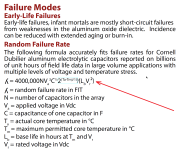
Cornell Dubilier, a manufacturer of electrolytic capacitors, published an Application Guide which I have attached below. Pages 13-14 discuss lifetime ("rate of random failures"). Notice that failure rate is exponentially dependent on temperature (light blue box).
_
_
Attachments
That application guide's tests are interesting, and reconditioning high DCL units. So, using a cap rated higher (well) than expected voltage more than makes sense from an endurance / lifespan perspective. I was looking at caps with very high hour rating, but that seems like spending more money than necessary, at least in this case.
Are there any brands to stay away from on Mouser or Digikey? Or are they all generally reliable.
Are there any brands to stay away from on Mouser or Digikey? Or are they all generally reliable.
I,m 54, and I have no illusions, all of this stuff should outlast me!8000 hours will last your lifetime. Maybe someone else's as well.
Open up your 50 year old Threshold power amplifier that's still working great, and see which capacitors they used.
Open up your 50 year old Levinson power amplifier that's still working great, and see what capacitors they used.
Open up your 35 year old Krell power amplifier that's still working great, and see what capacitors they used.
Open up your 50 year old Levinson power amplifier that's still working great, and see what capacitors they used.
Open up your 35 year old Krell power amplifier that's still working great, and see what capacitors they used.
Hi All,
Probably a dumb question, but I'm not seeing any marking on the PCB for polarity for LED2 and LED3. Just wondering if the anode of the LED is facing R9 and R10 respectively, or towards the bank of filter resistors? Thanks for any help here!
Probably a dumb question, but I'm not seeing any marking on the PCB for polarity for LED2 and LED3. Just wondering if the anode of the LED is facing R9 and R10 respectively, or towards the bank of filter resistors? Thanks for any help here!
Link to schematic is in post 1, and now here,- https://www.diyaudio.com/forums/ima...mentation/P-PSU-1V30/P-PSU-1V30-schematic.pdf. You can meter continuity from LED2 to R20 and LED3 to R21 to be sure.
Bought these from Digikey, Nippon Chemi-con 22000uF, 63v, $4.84 each when you buy ten. Be aware, at 2.638/67mm they are tall.
https://www.digikey.com/en/products/detail/chemi-con/ESMH630VSN223MA65S/4002920
https://www.digikey.com/en/products/detail/chemi-con/ESMH630VSN223MA65S/4002920
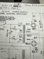
I'm in the process of building Nelson's AB100 amp, using the diyAudio version 3 power supply board and an Avel-Lindberg toroidal transformer with dual 115v primaries and dual 35volt secondaries (Model Y236852). I'm using ordinary 600 volt, 35 amp bridge diodes. I expect to get somewhere around 47 volts DC output from the supply, so I'm using 8 x 15,000 microfarad caps, rated at 63 volts and 105 C. [ BTW, I've built the standard CRC filtered, 24 volt DC, version of this supply 3 times before (for my F5, my F6, and my Aleph J), using Antek's 6218 transformer and lower DC voltage-rated caps. This PS has worked great in each case. And 6L6's excellent build guides have made building and using this supply easy and fun.]
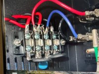
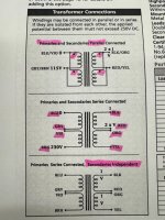
My question: When I look at the schematic for the new Avel Lindberg transformer, I see that the "Hot" and "Neutral" designations for the two primaries in parallel are reversed from those printed in red ink ("A 120" and "A 0", and "B 120" and "B 0") by 6L6 on his annotated schematic for the diyAudio supply, using what I assume is an Antek transformer. On the Avel Linderg unit, a "0" designation appears at the top of the schematic for each paralleled primary winding, and "115V" appears at the bottom of each. (see photo below). What should I do, if anything, to accommodate this difference? Should I reverse the "hot" and "neutral" AC input leads that attach to posts #3 and #2, respectively, on the Terminal strip? (see upside down photo from 6L6 below). (BTW, There is no earth ground connection for this transformer, if that is relevant.)
[If I can get past this issue, I have another question related to phase relationships between the secondary windings, but since these windings are independent, as used by this bipolar P.S., and each feed an independent bridge diode, maybe this is irrelevant too. I've never worried about it before because Antek does not show phase dots on their schematic. Ignorance=bliss?]
Attachments

Answering your question, the important bit is that the primaries are not inside-out in relationship to each other. If they are wired inside-out, you'll almost be blowing fuses on start.
Do you need to reverse the Live and Neutral at the terminals? Looking around its not immediately obvious if there's a standard to the lead winding getting hot or neutral, you can find it drawn both ways, but perhaps it's more common with hot to the trail winding?
When in doubt, connect as shown on the manufacturer's data. It's easy enough.
Antek actually does show phase, as it's implied in the schematic, but yes, they are sans-dots.
- Home
- Amplifiers
- Power Supplies
- diyAudio Power Supply Circuit Board v3 illustrated build guide