Thank you 6L6 for the very fast reply! I don't understand what you mean by wiring the primaries "inside -out" (other than that it sounds like "double-plus ungood", as some sage once said).
Sorry to be a bit of a dim bulb about this, but I guess what I am asking is: if I simply reverse the hot and neutral input leads to terminal posts #2 and #3 will that work to "connect as shown on the manufacturer's data" sheet (which is what photo image 8041 above shows), without creating other problems, such as defeating the surge protection of the thermistors, or what have you. Thank you very much for your patience and your help.
Sorry to be a bit of a dim bulb about this, but I guess what I am asking is: if I simply reverse the hot and neutral input leads to terminal posts #2 and #3 will that work to "connect as shown on the manufacturer's data" sheet (which is what photo image 8041 above shows), without creating other problems, such as defeating the surge protection of the thermistors, or what have you. Thank you very much for your patience and your help.
Yes, if you reverse your live and neutral connections to the terminal post, the transformer will connect as shown on the datasheet. Everything else will work as normal.
Hi 6L6: I've completed the wiring on my power supply for my Pass AB100, and was ready to set things up with my Variac to test the supply. But I ran across a few threads yesterday concerning the use of the CL-60 thermistors in series with transformer primaries in FW amps, which got me thinking/worrying. In building my F5, my F6, and my Aleph J, I used these devices with transformers rated for 625 VA and a standard CRC filtered PS build with 8 X 15,000 microfarads, yielding + - 24 vdc, and everything worked great (although I am surprised to learn now that these devices run so hot in normal operation! I never measured them in previous builds).
This time I'm again using a dual-primary 625 VA transformer but the secondaries are rated at 35 vac, and my supply may yield 47 vdc. Caps are still 8 X 15K (63 v), but I have left off the CRC filter resistors and installed jumpers instead, in line with comments in these forum threads which indicate somewhat less value using a CRC configuration with a class AB amp.
Do you thinks that the CL-60 devices will be adequate under these changed conditions? I saw a recommendation from Mark Johnson for an alternative device with greater joule surge rating, and possibly better long term reliability, but again that was for a FW amp with about half the DC supply voltage.
The math for estimating post-surge current for my AB100 is not real clear to me.
Adequate for what? Working normally? Yes, I don't see why not, as they are rated for 5A each and you have two that are effectively in parallel.
Yes, they get (quite) hot in normal operation. Being Negative Temperature Coefficient, it’s logical that the change in resistance happens with a change in temperature.
Good call on jumpering the filter R. That’s a perfectly good idea with an AB amp.
Yes, they get (quite) hot in normal operation. Being Negative Temperature Coefficient, it’s logical that the change in resistance happens with a change in temperature.
Good call on jumpering the filter R. That’s a perfectly good idea with an AB amp.
625VA / 115V RMS = maximum steady state current in transformer primary = 5.44A RMS . @6L6 is correct, sending half of that through one CL-60 and the other half of that through a second CL-60 is well below the CL-60's rating: (5.44 / 2) is well below 5.
The manufacturer's engineering datasheet for the CL-60 says that when 2.50 amperes are flowing ("50% of rated current"), the CL-60's resistance is 0.44 ohms. We can calculate the power dissipated in the CL-60 in this condition: Power = RMScurrent * RMScurrent * resistance ; 2.50 * 2.50 * 0.44 = 2.75 watts dissipated by the CL-60. No wonder the darn thing gets hot!!
Of course Amphenol has competitors who make and sell their own line of inrush current limiter discs. One such competitor is Ametherm, who makes an apparently identical twin to the CL-60. The part number of Ametherm's identical twin is SL18-10005 , and its max steady state current is 5 amperes (same as CL-60). Its resistance at room temperature with no current flowing is 10 ohms (same as CL-60). Its resistance with 50% of rated current flowing is 0.44 ohms (same as CL-60). And, happily, Ametherm actually tells you the ICL disc's body temperature when 5 amps are flowing (see below), it's One Hundred Eighty Degrees Celsius! Cowabunga, that thing is hot. I bet the Amphenol CL-60 is the same or very close, but they don't publish that number in their datasheet. I've got a Parasound power amp which includes an Inrush Current Limiter disc. Parasound installed a thermal "sock" around the disc to prevent it from destroying nearby components and burning repair technician's fingers.
_
Attachments


Many thanks to 6L6 and Mark Johnson for clarifying things for me! Especially so quickly. I will find a 6 amp slo-blow fuse in my bin of parts, install it in the panel mount, and get my variac up on the bench for a PS test. I have the CL-60 devices installed where they will get some air. And any wires in the area (in fact, all wires in the amp except for the transformer leads) are teflon insulated so they can take a little heat.


According to Nelson in his post: https://www.diyaudio.com/community/threads/ab100-class-ab-power-amplifier.227503/post-3320314, the bias current of the AB100 is 0.08A per channel.
So there is a large inrush current at power up. Then the speaker sensitivity and music loudness would determine ongoing power supply current.
Also current at 120VAC is about one third of current at 47VDC.
For a Class AB amplifier are thermistors in series with the power supply a good thing if the current varies, and therefore the resistance of the thermistor varies?
Last edited:
6 Amp slo-blow? Where did you come up with that number?
EDIT: oh... 625VA transformer. 6 is a bit high, but absolutely in the ballpark.
EDIT: oh... 625VA transformer. 6 is a bit high, but absolutely in the ballpark.
Last edited:
Yeah, I was just sitting here thinking "Uh, wait a minute, if the maximum steady state current of the transformer is 5.44 amps RMS, why in the world would I choose to pick a fuse value above that? Where is the protection in that? Duh!!" And I listen to music in a small room! I'm only building the AB100 to see if it makes my power hungry Magnepans sound a little more alive. Maybe I should start with a 3 or 4 amp slo-blow and see how that works. My Aleph J is fused at 3 amp.
The Aleph J was easier since I had a great build guide to follow. Only had to puzzle over metalwork.
build a pair of F6es or M2xes and run them balanced (or if you have a preamp that will drive them, a pair of F4s).I'm only building the AB100 to see if it makes my power hungry Magnepans sound a little more alive. Maybe I should start with a 3 or 4 amp slo-blow and see how that works. My Aleph J is fused at 3 amp.
The other day, I set up the power supply for my AB100 with a variac and brought it up slowly, using a slo-blo 4 amp fuse in the AC fuse holder. No smoke or other drama! At about a "110v" setting on the variac, the power supply put out about 50 vdc (no load). Beyond the fact that there was no load attached, I wonder if I got a little bit of extra voltage output because I used jumpers instead of the CRC filter resistors.
The next day, I put the variac away and connected the power supply directly from a wall AC outlet, and flicked the amp AC switch on. Again, no drama, and the fuse held in this "instant on" trial. I got about 51 vdc (no load).
Thanks again to 6L6, Mark Johnson, Ben Mah, and 6sXy for helpful information and suggestions on the power supply.
I'm moving to finish stuffing the AB100 amp boards next, and then to mounting output transistors and wiring things up, and will post any questions and photos over in the AB100 thread. I'm sure there will be a pile of those, since I chose input, drive, and output transistors in sort of a smorgasbord manner. (Gulp!). The output units will be the TO-3 devices Osscar used. ( I did this for mostly nostalgic reasons, since the Leach Amps I build in 1978, 1990, and 2009 all used TO-3 transistors, and I like 'em.)
Aleph J:
200W of constant dissipation (2A per each AMP PCB, power supply rail is close to 50V).
The transformer's (worst case assumption: pretty low-quality transformer) efficiency is 90 %. Hence, we have 200 + 200 x 0.1 [VA] on the primary side => from the mains outlet, we have 220 VA of power consumption. So: 240V AC, one CL60, 220VA => current trough the CL60 is approximately 0.9A. The CL60 will get hot... but nowhere near 180degC hot.
Class A/B amplifier:
The above calculation also works the same, but the power consumption on the secondary side is negligible. Hence, the CL60 used in class A/B amplifier will never get hot - its resistance will always be too high (cold-state resistance) most of the time - this is the first undesirable element. As the power consumption increases (listening to very loud, bass-heavy music), the CL60 will start to vary its resistance, and the sound character will be constantly changing - this is the second undesirable element.
Solution: It is a class A/B amp, so do not use more than 22,000uF caps (per each DC rail). The power-on surge will be okay... No need for CL60 in this case. Just use connected in series, a snubbing combination of a capacitor and resistor, right across the mains power switch contacts.
Hi, I assembled the power supply board, but I realized, that the heatsink covers some THT holes and looks close to the diode pads. I think it would be difficult to revoce it completly, but maybe I can lift it by 0.5-1mm. Is it safe enough?


remove 2mm of metal from the heatsink using a file, apply a piece of kapton insulating tape to the heatsink, apply another piece of kapton tape to the PCB
Everything is soldered, and the pin is so tight in the hole, so I was able only lift it. Now I have 1.5-1.6mm airgap between the PCB and the heatsink.

I'll try to put some insulation there.
I'll try to put some insulation there.
I see that you cleverly electrically isolated the metal back of the diode, which likely is your cathode, from the heatsink. I also noticed that there are traces that connect the two outer pads of the diodes, which are likely the anodes. Shorting the two anodes through the heatsink... I can't see that being an issue, but wiser people would know with more certainty. Shorting the anodes to the cathode would likely be an issue, but your insulator solves that.
Have you done a "beep and wiggle" test to see if there is anything that may be of actual concern? Set your DMM to resistance / continuity and check. Do your best to wiggle the parts and see if anything ever makes contact to something that would cause an issue.
Again, smarter people than I should weigh in.
Thanks for the reply. As far as I know, anodized aluminum is not conducive, that could be the reason why DMM continuity test didn’t show any short circuit. I checked before I lifted it.
Now with 1.5mm air gap should be ok.
Now with 1.5mm air gap should be ok.
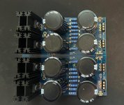
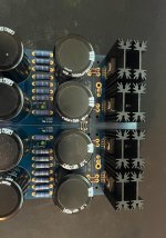
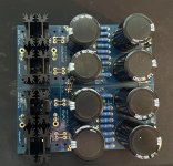
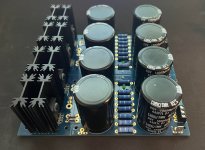
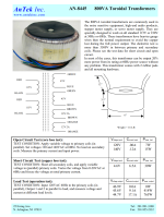
Hi, I am new to the forum(and DIY audio in general) and recently decided to try and build the Honey Badger power amp. I'm using the universal power supply in conjunction with the soft start board, but am running into some problems. Attached are some images of my "completed" power supply. I am using the Antek AN-8445 - 800VA 45V Transformer, but I'm not quite sure how to wire it properly. I attached the red and black wires of the transformer to the XFR2 and XFR1 locations on the soft start board, attached the 45 V green wires of the transformer to the AC1A and AC1B locations on the power supply, and the 45 V blue wires to the AC2A and AC2B locations. However, when I test the functionality of the power supply using a 100 W dim bulb tester, the bulb lights up and stays lit with a voltage drop of 35 V across it. When doing this, the DC voltage output of the power supply reads 4.0 V on my DMM. I assume there must be a short somewhere in the circuit for the bulb to stay lit, correct? Could somebody please verify that I have soldered the power supply components correctly, and that I am wiring the transformer in the correct locations? Any help is greatly appreciated!
Attachments
- Home
- Amplifiers
- Power Supplies
- diyAudio Power Supply Circuit Board v3 illustrated build guide