You do not have the transformer secondaries wired correctly.
Each secondary winding is terminated by one green and one blue wire. Using your meter set to Ohm (resistance) measure a pair of green and blue wires. You want to find one set of green and blue wires that measure a low resistance. The other set of green and blue wires should then also measure a very low resistance.
With these sets of wires, one set of blue and green wires connect to AC1A and AC1B, and the other set connects to AC2A and AC2B.
Thanks! Rewiring the transformer seems to have done the trick. Light bulb lights then dims, and power supply is reading +/- 64 V.

Hi,
Need some help regarding the PSU parts for the Honey Badger build.
I have a separate thread open for it here:
I'm an IT engineer, been doing it for almost 20 years, and trying to get into this hobby as I love music and soldering. And I need all the help I can get...
and the questions are in post #14. Or if needed, I can summarize my questions and post it here, whatever works better.
Many thanks in advance! Cheers!
Need some help regarding the PSU parts for the Honey Badger build.
I have a separate thread open for it here:
I did but not all things are clear to me, that's why I'm asking questions here. Also I did search the threads on the forum and there are so many conversations about things that are touching the subject but not explaining directly what I need that I could not extract the needed information with confidence.Why don't you read through some of the docs linked off the store: https://diyaudiostore.com/products/honey-badger
jeff
I'm an IT engineer, been doing it for almost 20 years, and trying to get into this hobby as I love music and soldering. And I need all the help I can get...
and the questions are in post #14. Or if needed, I can summarize my questions and post it here, whatever works better.
Many thanks in advance! Cheers!
C1 - C8
https://au.mouser.com/ProductDetail/Cornell-Dubilier-CDE/380LX103M080A052?qs=sGAEpiMZZMvwFf0viD3Y3T2mGac%2BTKhA/dpqs3b5vEY=
CX1 – CX2, CS1 – CS2
With the choice of your fast-switching soft recovery diodes, you probably won't need these... especially if the transformer secondary leads are not cut very short. To properly dampen the secondary/didoes "tank", you'll need an oscilloscope. If you over-dampen, the sound will suffer (loss of details, loss of spatial sound/air, loss of transients' attack). In other words, you need to leave just a bit of overshoot... but prevent ringing.
C1 - C8 I guess these ones will work too then?
https://www.digikey.ca/en/products/detail/nichicon/LLS1K103MELC/2548907
Regarding diodes, I don't know which one to choose. What is your recommendation, FEP30DP-E3/45 or MBR20200CT?
Thank you!!!
https://www.digikey.ca/en/products/detail/nichicon/LLS1K103MELC/2548907
Regarding diodes, I don't know which one to choose. What is your recommendation, FEP30DP-E3/45 or MBR20200CT?
Thank you!!!
Hello again! Please find attached BOM for the PSU. Transformer is Antek 45 0 45 800VA.
There is a link for all the parts inside including questions regarding substitute parts and replacements.
If someone can take a look and tell me if this is good enough so I can order parts....
Thank you!
There is a link for all the parts inside including questions regarding substitute parts and replacements.
If someone can take a look and tell me if this is good enough so I can order parts....
Thank you!
Attachments
Hi All,
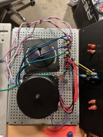
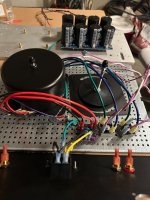
I'm looking for some community help as I'm beginning to get really frustrated with my PSU build on my F6. I'm in North America and on 120V, and using an Antek AS-2218 toroidal with the plan to go dual mono if I can figure out what is off here. Two big things are bugging me right now
Any guidance on either item above would be super helpful. I've built a PSU for a phono stage before and had none of these troubles so am quite confused. I've swapped diodes, swapped transformers, changed fuses, and have tried to measure at every step in the circuit and can't figure it out. Pictures and datasheet for my transformer are below. White wires coming from diodes are negative and purple are positive.
I'm looking for some community help as I'm beginning to get really frustrated with my PSU build on my F6. I'm in North America and on 120V, and using an Antek AS-2218 toroidal with the plan to go dual mono if I can figure out what is off here. Two big things are bugging me right now
- My voltages are low. With 18V secondaries I'd expect 18V*1.4 = 25.2-1.4 for diodes= 23.8V or therabouts post diodes but I'm getting 15V instead. I did check my AC and it's running at about 116V and after the safety cap and CL-60 I've got 110V, which seems like a steep drop for that one section. I did check that I have 17V going into my diodes.
- When I connect the diodes to my PSU PCB I get maybe 4V and the number falls over time. My bulb glows bright then dims and my LEDs do turn on but they're super dim. I've checked my soldering, made sure my ground connections were correct and besides some scratches on the PCB everything looks good to my eyes.
Any guidance on either item above would be super helpful. I've built a PSU for a phono stage before and had none of these troubles so am quite confused. I've swapped diodes, swapped transformers, changed fuses, and have tried to measure at every step in the circuit and can't figure it out. Pictures and datasheet for my transformer are below. White wires coming from diodes are negative and purple are positive.
Attachments

It's hard to tell, but it looks like you've negated the function of your ground break thermistor, but that shouldn't have that big an impact.
Did you check both rails?
Did you ensure that you separated the transformer secondaries properly? Did you measure the ACV at both secondaries? You say...
You checked both diodes?
Did you check both rails?
Did you ensure that you separated the transformer secondaries properly? Did you measure the ACV at both secondaries? You say...
That (with a 200VA transformer with no load) seems a tad low to me, but with 110VAC in... that could be about right.I did check that I have 17V going into my diodes.
You checked both diodes?
How are you measureing this at the diodes? Since it's not "smoothed yet", neither and ACV or a DCV from a DMM isn't terribly reliable. That seems about right.My voltages are low. With 18V secondaries I'd expect 18V*1.4 = 25.2-1.4 for diodes= 23.8V or ther abouts post diodes but I'm getting 15V instead.
Last edited:
Measuring everything with a DMM. I have 15VDC coming off the diodes. I'd be okay with being in the 20V range compared to the 23.8VDC I'd expect, but 15 seems quite low. I'll double check both diodes again but have already swapped them out once with similar results, so I don't think it's the individual diodes.
I do have a thermistor connected to safety ground to elevate the PSU ground from chassis ground, is that the incorrect connection spot?
I do have a thermistor connected to safety ground to elevate the PSU ground from chassis ground, is that the incorrect connection spot?
To second ItsAllInMyHead, check that the secondary leads are separated correctly (i.e. paired per continuity between a blue and a green lead.)
If you have 17Vac coming off of those and both pairs have been verified, points to an issue with the diode bridges. Do you have datasheets for those particular part numbers?
If you have 17Vac coming off of those and both pairs have been verified, points to an issue with the diode bridges. Do you have datasheets for those particular part numbers?
I wouldn't worry about this for now, but it looks like the "audio ground side" of the thermistor is making contact with the mounting plate for the transformer. Hard to tell in the photo. Either way, that shouldn't cause your issue.I do have a thermistor connected to safety ground to elevate the PSU ground from chassis ground, is that the incorrect connection spot?
Your DMM set to DCV isn't seeing a nice perfect flat DC, since it's not smoothed yet. I personally don't give this a second thought, but... I could be wrong.I have 15VDC coming off the diodes
I'm puzzled how you get 4VDC out of the filter boards.
Once again... did you measure both rails? I assume you aren't also using a Variac and ... accidentally turned it "back down" for another measurement. I've NEVER done that...

Last edited:
@Calvdart Hmmm… this is a mystery, as there’s nothing that seems obviously incorrect in your photos, but your measurements are unquestionably strange.
Ok, let’s start isolating variables.
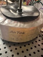
1) Open up the can and pop out the transformer, make sure they sent you a 2218. Post a photo of the label here please.
2) Remove the transformer primaries from the Thatcher AC thermistor/cap board and make sure you've got 120VAC at the output terminals. This will require measuring mains AC, take appropriate precautions and be careful. You may have done exactly this? If so skip it.
3) As previously suggested, make sure your secondaries are properly paired, the blue must have continuity with the green you use on that particular diode bridge.
4) What is the measured VAC of the secondaries?
5) When all is attached and switched on, is the ground breaker thermistor getting hot?
Ok, let’s start isolating variables.
1) Open up the can and pop out the transformer, make sure they sent you a 2218. Post a photo of the label here please.
2) Remove the transformer primaries from the Thatcher AC thermistor/cap board and make sure you've got 120VAC at the output terminals. This will require measuring mains AC, take appropriate precautions and be careful. You may have done exactly this? If so skip it.
3) As previously suggested, make sure your secondaries are properly paired, the blue must have continuity with the green you use on that particular diode bridge.
4) What is the measured VAC of the secondaries?
5) When all is attached and switched on, is the ground breaker thermistor getting hot?
Thanks for the help so far, everyone.
Quick update @6L6 and @ItsAllInMyHead - No variac in my power chain yet. I confirmed I'm pulling a little over 16VDC from one diode and a little under 15VDC after the other. Both rails post caps are at +/- 4VDC. I removed the steel cover to try and simplify things a bit and confirmed I have an AS-2218 (photo below). I even switched out the diodes I was using (datasheet for those also below) for a set I got from Thatcher when I bought the PCBs and getting the same results. When I measured the output side of the Thatcher thermistor/cap board previously I had 110VAC but will double check that.
Going to finish up work and then start investigating the transformer. I have a 15V secondary Triad toroidal in a box somewhere that I plan to swap in and see if I get voltages more in line with what I'd expect.
Attachments
What you need to do is to start at the beginning.
Disconnect the power transformer secondaries from the bridge rectifiers.
Set your meter to VAC and measure each secondary pair (blue and green). They should measure approximately 18VAC.
Then connect the transformer secondaries to the bridge rectifiers. Disconnect the PS board from the bridge rectifiers. Power up and measure the DC voltage at the bridge rectifier output. With no capacitors attached, it should measure somewhere between approximately 13VDC and 16VDC.
Edit: Voltage should read approximately 18VDC or higher, not 13VDC to 16VDC.
If good so far, connect the bridge rectifier output to the PS board input. Measure the DC voltage between V+ out and Ground, and between V- out and ground. It should measure around 24VDC or so.
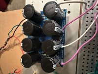
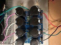
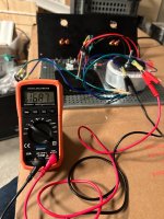
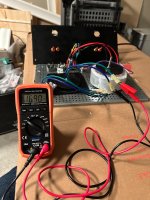
If the voltage out from the bridge rectifiers are good but the voltage out from the PS board is not, post pictures of your setup, showing all wires. Be sure to include a picture of the overall setup showing all wires and connections. Also include a picture of your meter connections to the board and the meter reading.
Disconnect the power transformer secondaries from the bridge rectifiers.
Set your meter to VAC and measure each secondary pair (blue and green). They should measure approximately 18VAC.
Then connect the transformer secondaries to the bridge rectifiers. Disconnect the PS board from the bridge rectifiers. Power up and measure the DC voltage at the bridge rectifier output. With no capacitors attached, it should measure somewhere between approximately 13VDC and 16VDC.
Edit: Voltage should read approximately 18VDC or higher, not 13VDC to 16VDC.
If good so far, connect the bridge rectifier output to the PS board input. Measure the DC voltage between V+ out and Ground, and between V- out and ground. It should measure around 24VDC or so.
If the voltage out from the bridge rectifiers are good but the voltage out from the PS board is not, post pictures of your setup, showing all wires. Be sure to include a picture of the overall setup showing all wires and connections. Also include a picture of your meter connections to the board and the meter reading.
Last edited:
To follow on, stop changing variables. Follow Ben Mah's advice. Check out the Antek 1st. Once the xformer is a known good state, add the diodes and check. Once the diodes are a known good state, add the filter board and check. Post pictures of each stage with the meter showing measurements.
I feel like I laid all of this out in my original post but will try to restate more clearly here along with photos. I've been checking that I have the correct pairs from the transformer with the ohm meter and continuity function on my DMM all along.
Which gets us all back together. I don't think it's the diodes because I've tried two sets with very similar results. I don't think it's the safety cap/thermistor board given the output there. The filter board is in another room so pretty sure it's not that either. Which leaves the transformer. The only other thing I can think of are the connections themselves but that seems like a low probability source of problems
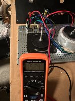
- Output from safety cap and thermistor is 118VAC per DMM. "Checks out, onto the next step"
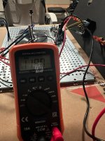
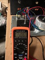
- Output from transformer secondaries (should be 18V) are 16.9VAC. "Don't love that it's not 18 but close enough for now."
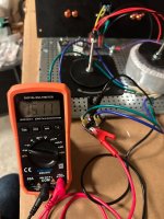
- Output from mouser diodes are 15.2VDC and 15.0VDC. "Hmm, that's too low. Maybe my diodes are bad? Let's try another set of diodes I have on hand."
- Output from diodes I got from Thatcher are 15.11VDC and 15.13 VDC. "I like the consistency there but still too low."
Which gets us all back together. I don't think it's the diodes because I've tried two sets with very similar results. I don't think it's the safety cap/thermistor board given the output there. The filter board is in another room so pretty sure it's not that either. Which leaves the transformer. The only other thing I can think of are the connections themselves but that seems like a low probability source of problems
Attachments
-
 safety cap and thermistor output.jpg494.4 KB · Views: 48
 -
 secondary output 1.jpg445.1 KB · Views: 39
 -
 secondary output 2.jpg469.1 KB · Views: 43
 -
 mouser diode output 2.jpg450.4 KB · Views: 47
 -
 mouser diode output 1.jpg428.9 KB · Views: 41
 -
 thatcher diode output 2.jpg373.3 KB · Views: 46
 -
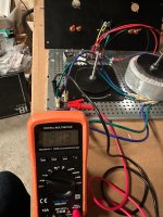 thatcher diode output 1.jpg456.8 KB · Views: 44
The transformer secondary voltages are low.
What is VAC from the wall? OK, I see that it is118V.
What is the VAC measured at the transformer primaries as connected?
Please show pictures of your circuit between the IEC and the transformer.
You can connect the transformer directly to the AC without any other circuitry in place and measure the secondary VAC.
Last edited:
Do you have, or can you borrow another DMM? Everything you are measuring with that meter is measuring low. Let's eliminate the test equipment from the equation.
Dan
Dan
- Home
- Amplifiers
- Power Supplies
- diyAudio Power Supply Circuit Board v3 illustrated build guide