That cap is mainly for spark suppression across the mains switch, and must be rated X1, Y2 for attachment across the AC line.
Here's a suitable part - DE2E3KY332MN2AM01F Murata Electronics | Mouser
Do I actually need this part?
thanks Jim.
And the snubber resistors, R11 & R12, are not used as far as I can tell. Can you confirm that is the case and, if not, why not?
I've read elsewhere in this thread that (paraphrasing here),"properly used snubbers for bridge rectifiers should be used". At least I think it was this thread.
And the snubber resistors, R11 & R12, are not used as far as I can tell. Can you confirm that is the case and, if not, why not?
I've read elsewhere in this thread that (paraphrasing here),"properly used snubbers for bridge rectifiers should be used". At least I think it was this thread.
R11, 12, C17, 18 are the output snubber. Leave open.
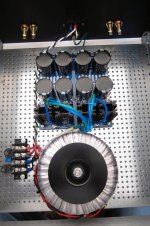
Cx1, Cs1, Rs1 and Cx2, Cs2, Rs2 are the input snubbers and are quite helpful, though not required. Go to the Quasimodo results thread and see if you can find your transformer's values there.
Cx1, Cs1, Rs1 and Cx2, Cs2, Rs2 are the input snubbers and are quite helpful, though not required. Go to the Quasimodo results thread and see if you can find your transformer's values there.
thanks Jim.
And the snubber resistors, R11 & R12, are not used as far as I can tell. Can you confirm that is the case and, if not, why not?
I've read elsewhere in this thread that (paraphrasing here),"properly used snubbers for bridge rectifiers should be used". At least I think it was this thread.
Chucked,
I recommend you read the No math Quasimodo test jig paper written by Mark Johnson and is posted on the Quasimodo site. Especially the first 8-10 pages or so. Skip the the Appendices unless you are really into it. You will learn some good stuff. The site 6L6 referred you to has results only. My problem has been that I have 8 transformers and none have been posted. YMMV
I am going through the Quasimodo solution right now because it is the best way to stop a big source of noise problems. It comes up repeatedly.
Let us know what you think. Try not to get overwhelmed by all the "stuff".
Good luck.
Regards,
Don
thanks Don and Jim. I'll look through that document.
I think the last question I have is the ground chassis. I have looked through the thread here and elsewhere and I am just a little unsure about how to go about wiring the star ground.
As far as I can tell from Nelson Pass' F5 Turbo Power Supply schematic, there is a thermistor in series from the ground pin on the AC line in to the chassis. There is also a diode array (35A, 200V), I think in parallel.
I also think I read that the CL-60 in series from the ground pin on AC line in to chassis is an alternative.
Do I have that right?
And if not how do I go about wiring the ground chassis? I couldn't work it out from any photos. 😕😕😕
No! AC ground must go directly to chassis for safety. CL-60 goes between power supply ground and chassis ground to provide some resistance to hum and protect in the event of a power supply failure by conducting and blowing the fuse.
Just saw this.
No. Don't do that. One thermistor in series with the AC primary only.
The other CL-60 goes on the output of GND at the power supply.
thanks WKCox. Your reply and the photo from 6L6 in post #896 helped.
Jim, why in that photo do you have a yellow and a green wire from the AC GND twisted together?
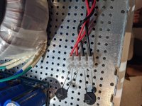
Here's what I have at the moment. That CL-60 will connect to chassis ground when that's done. Does that all look good?

Because in many countries Safety Earth is green wire with a yellow stripe. So I used what I had on hand to make it look pretty close... 🙂
Are the black and red primary wires on the transformer interchangeable? Not between the colours but there's a long and short pair. Do you have to pay attention to the location when connecting to the euroblock?
Not sure if that's very succinct...
Not sure if that's very succinct...
Assuming you have an Antek transformer, there are usually two primaries, with a red and black wire for each primary. To identify the wires for each primary, check the resistance of the red - black pairs. A pair of wires will measure infinite resistance (open circuit) if they are not of the same secondary. The correct pair of red - black wires of a secondary will measure a low resistance (have continuity).
Yes, you need to identify the wires for each primary and then connect them in accordance with the schematic.
Yes, you need to identify the wires for each primary and then connect them in accordance with the schematic.
Assuming you have an Antek transformer, there are usually two primaries, with a red and black wire for each primary. To identify the wires for each primary, check the resistance of the red - black pairs. A pair of wires will measure infinite resistance (open circuit) if they are not of the same secondary. The correct pair of red - black wires of a secondary will measure a low resistance (have continuity).
Yes, you need to identify the wires for each primary and then connect them in accordance with the schematic.
Thanks for response. I don't think I asked the question very well.
I need to connect the primaries to the barrier strip with the CL-60s and safety cap. The wiring has the two black wires in position 1 & 2 and the two reds in 3 & 4.
I am wondering if either black wire can go in position 1 & 2? And if either red wire can go in 3 & 4? I think they can I just want to confirm since there is clearly a longer red/black pair and a shorter red/black pair.
Attachments
Again, I have to stress that you have to identify the red and black wires that belong to each primary. You should label one pair of primary wires "A" and the second pair of primary wires "B". Then the AC live goes to Red "A" and the AC neutral goes to Black "B".
This is assuming you are building a FW power supply with an Antek transformer at 120VAC.
This is assuming you are building a FW power supply with an Antek transformer at 120VAC.
Attachments
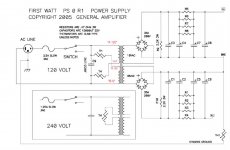

If the schematic + diagram of the transformer is still a bit over your head, do exactly as suggested in steps:
Separate each pair of wires for the primaries with a continuity check. Identify them in some way.
Then, this may help. I've seen this physical implementation in a number of builds.

Separate each pair of wires for the primaries with a continuity check. Identify them in some way.
Then, this may help. I've seen this physical implementation in a number of builds.
Again, I have to stress that you have to identify the red and black wires that belong to each primary. You should label one pair of primary wires "A" and the second pair of primary wires "B". Then the AC live goes to Red "A" and the AC neutral goes to Black "B".
This is assuming you are building a FW power supply with an Antek transformer at 120VAC.
For some reason Antek's trafo wiring diagrams are loosing their phase dot but the diagram on the trafo itself still has it.
All Anteks are probably built the same but I have never really understood how you can tell which secondaries are the "dot" secondaries.
Thanks,
Don
As far as I can tell, all Antek transformer wires have have two different colours for each winding, and they are phase consistent, so the colours can be used.
Again, I have to stress that you have to identify the red and black wires that belong to each primary. You should label one pair of primary wires "A" and the second pair of primary wires "B". Then the AC live goes to Red "A" and the AC neutral goes to Black "B".
This is assuming you are building a FW power supply with an Antek transformer at 120VAC.
Yes it is an Antek AN-6225. And yes 120VAC for F5Tv2.
Thanks for clarifying. This is clearer to me. I just powered it up and everything worked just great. I will be doing a build guide similar to 6L6 when the gain stage is done.
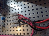
But back to this....(I couldn't label the image easily on my computer). I could work out the two red/black pairs easily. The A pair is in the middle of the barrier strip.
I had the AC live (red in my case) to RED A but actually had the neutral (black in my case) to BLACK A, not BLACK B, contrary to what you suggest. See photo. I was looking at 6L6 photo (also attached). He has the neutral (white) going to RED and the live (black) going to BLACK , contrary to Allinmy head image.
I can't tell what pair they are, hence, my initial question: Given this is AC, does it matter how the live and neutral wires are connected, so long as they are connected to a red and a black.
Attachments
Did you identify the red-black pairs for each secondary? If not, then you need to disconnect and identify them.
Then wire everything up as diagrammed.
The live and neutral may be flipped, but the connection must be to Red A and Black B.
But if you don't understand what is going on and you are just connecting wires, you should follow the instructions exactly. You are dealing with live electricity and mistakes may be deadly.
The power switch and fuse must be on the live line.
- Home
- Amplifiers
- Power Supplies
- diyAudio Power Supply Circuit Board v3 illustrated build guide