That cap is mainly for spark suppression across the mains switch, and must be rated X1, Y2 for attachment across the AC line.
Here's a suitable part - DE2E3KY332MN2AM01F Murata Electronics | Mouser
Here's a suitable part - DE2E3KY332MN2AM01F Murata Electronics | Mouser
Marc,
attaching a capacitor or suppressor across the On/Off switch will partially defeat the Off function.
Some equipment would continue to operate using the power passing through the switch bypass.
All equipment that uses a cap across the switch will leave the equipment Live when the switch is Off !
Spark suppression should be across the load. That preserves the Off function of the switch and works just as well at protecting the switch from excessive voltage sent back from inductive loads.
Spark suppression should be across the load. That preserves the Off function of the switch and works just as well at protecting the switch from excessive voltage sent back from inductive loads.
Andrew, looking at the schematic for PSU v3, what qualifies as a load, across which to locate the spark suppression cap?
Do CX1 and RS1 (in the snubber circuit) perform any kind of spark suppression?
Attachments
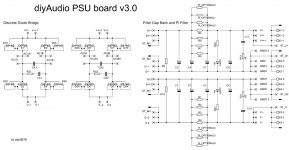
Those diagrams are on the secondary side of the isolating transformer.
I think the switch you are asking about is on the primary side of the transformer.
I think the switch you are asking about is on the primary side of the transformer.
So do I just add a small value resistor and the cap across the primaries?Those diagrams are on the secondary side of the isolating transformer.
I think the switch you are asking about is on the primary side of the transformer.
Mains Connections
I did find some nice explanations of mains connections on Rod Elliott's pages:
I did find some nice explanations of mains connections on Rod Elliott's pages:
An externally hosted image should be here but it was not working when we last tested it.
An externally hosted image should be here but it was not working when we last tested it.
I don't agree with the way both those diagrams are wired.
I think the top one should have the fuse before the switch.
The bottom one has no convenient location to place the snubber across the load. that is because the fuse is on the wrong side of the switch.
You could place the snubber across the Neutral and Live of the switch, but the fuse if or when it ruptures breaks the connection.
If the Live goes to Fuse first and then goes down to the switch, then a snubber across the L & N, on the load side, of the switch is effectively across the load even if the fuse ruptures. Opening the switch, or rupturing the fuse, now activates the snubber action.
I just ordered the Soft Start and Speaker Protection boards from the diy audio store so that should take care of my problems.😉
Build the amp first as published. Then add the Soft Start, then the Speaker Protection.
Don't try to do it all at once.
Don't try to do it all at once.
The DIYaudio soft start board is powered direct from the Mains supply.I just ordered the Soft Start and Speaker Protection boards from the diy audio store so that should take care of my problems.😉
This may be an example of a piece of equipment that continues to operate even though the mains switch is in the OFF position. The bypass capacitor may pass enough power to keep the soft start ON.
I think I will be stuffing the caps section with 4 x 80V, .01F (10,000uF) Nichicon caps per channel.
I plan on running approx. 67V rails from 2 x 0-45 secondaries.
1) What do the the PI resistors do, and how would I select the correct amount for my application? (Driving 2 Honey Badgers)
2) Would I omit C17-18(output snubbers) if I don't plan on using input snubbers?
3) I was gonna use YAGEO 10K, 1/2W, 1% Metal film resistors that I have on order for R20, and R21. I imagine that this would be suitable?
*Note: I plan on using the larger 3P package diodes if that matters
Last edited:
From the little bit I understand, I think these guys are to drop the voltage peaks to create smoother DC. Am I off base here? Would love to read a good source about PSU filters, etc.I think I will be stuffing the caps section with 4 x 80V, .01F (10,000uF) Nichicon caps per channel.
I plan on running approx. 67V rails from 2 x 0-45 secondaries.
1) What do the the PI resistors do, and how would I select the correct amount for my application? (Driving 2 Honey Badgers)
I don't see them adding any value. I will omit.2) Would I omit C17-18(output snubbers) if I don't plan on using input snubbers?
I know this is OK, I'm not sure why I even asked 😎3) I was gonna use YAGEO 10K, 1/2W, 1% Metal film resistors that I have on order for R20, and R21. I imagine that this would be suitable?
2 out of 3 isn't bad 🙂
I've also decided to look for the monolithic bridges. They are compact, tidy, and I like saying "monolithic" !
Last edited:
A normal capacitor input filter using an electrolytic just after the rectifier is actually and rC filter.
The "r" of rC is the resistance of the circuit through the transformer and through the rectifier and all the wiring linking those to the capacitor, including the capacitor leads and it's own internal connections.
If you add on an extra filter stage you end up with rCRC where the "R" is the resistance of the wiring connecting the two capacitors and any resistor value you put into that wiring.
The CRC part is a Pi filter
But don't exclude the r. It is what creates the first filter.
PSUD2 is good for analysing this if you, like me, don't have the maths knowledge to calculate more complex filters.
Appreciate the explanation, it was very helpful! I will look for PSUD2 to play with. I'm thinking that the second R value (the resistance between CRC) is used to limit the discharge from the 1st C. Which I suspect would create less ripple.
On second thought, that doesn't seem right looking at the schematic.
On second thought, that doesn't seem right looking at the schematic.
Last edited:
The two RC filters form a cascade that has double the slope, i.e. a 2pole roll-off.
It's the extra RC AND the steeper slope that gives the extra filtering effect.
The second C ADDS to the load seen by the first C and as a result the first C sees a higher ripple current and can run hot/hotter.
You must ensure that the first C has sufficient ripple capacity to suit this new duty.
Again PSUD2 shows you this.
The intermediate R increases the source impedance of the first C as seen by the load. That reduces load performance. You make up for this by increasing the last C.
In the end you get less mains ripple and less mains HF interference in return for spending more on capacitors and spending more on ripple capacity.
The two RC filters form a cascade that has double the slope, i.e. a 2pole roll-off.
It's the extra RC AND the steeper slope that gives the extra filtering effect.
The second C ADDS to the load seen by the first C and as a result the first C sees a higher ripple current and can run hot/hotter.
You must ensure that the first C has sufficient ripple capacity to suit this new duty.
Again PSUD2 shows you this.
The intermediate R increases the source impedance of the first C as seen by the load. That reduces load performance. You make up for this by increasing the last C.
In the end you get less mains ripple and less mains HF interference in return for spending more on capacitors and spending more on ripple capacity.
Thanks for further clarification. The math/ theory is a bit beyond my current capabilities.
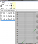
I was playing around in PSUD2, just for better understanding. I had to make a couple assumptions that I'm sure are not accurate, but should allow me to see the effect of the second RC. I kept the load at 5k (I do not know the actual load, but the effect should be the same regardless). These sims don't factor the bleed resistors, just the rCRC vs rC into a 5k load. The rCRC shows much less ripple using the 4 suggested 0R47 3W "PI Resistors", and 40kuF per rail. Does this seem like a reasonable simulation?
Attachments
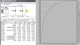
The results include the starting variations of voltage and current.
Ask the sim to start after a delay.
Try 10seconds delay, then 1second of display.
Ask the sim to start after a delay.
Try 10seconds delay, then 1second of display.
The results include the starting variations of voltage and current.
Ask the sim to start after a delay.
Try 10seconds delay, then 1second of display.
Thanks!
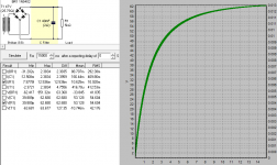
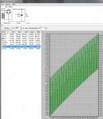
Using 47V Secondaries into 40kuF per rail; 10s delay; 1 Sec of display:
rC Vs. rCRC: The rCRC appears to reduce the ripple to approx. 60% of the original .9V ripple down to .5V ripple.
This would lead me to believe that using the suggested 4 x 0R47 3W resister(as simulated-except the false load) per rail would be a good improvement in this situation. Does that sound like a fair statement?
EDIT:
I mentioned ripple. I may have mis-spoken. The "swing" is what I should have said. The ripple in the 2nd graph is less than .02V
Attachments
Last edited:
- Home
- Amplifiers
- Power Supplies
- diyAudio Power Supply Circuit Board v3 illustrated build guide