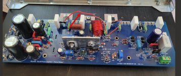
Thank you Chip! Yes, it's the Speaker Turn-on Delay and DC Protector board from the diyAudio store. It seems to be working OK so far.
On my fourth board. Built it carefully with some great help from UncleMud.
With first turn on with the DBT in place I got these values at 120ACV:
Both LEDs work
Current across each fuse = 0.430 +/- DCV
R7 is sitting at 8.07DCV
Loop IV = -0.793 DCV
R17 Offset = 005.2 mV
After 15 turns of R30:
Loop 1V moves from -0.795DCV to -1.049DCV
R7 = -08.18DCV
R30 = 00.0 mV
R17 = 7.9mV
I actually pushed R30 to 20 turns, but still no measurable value on R30, but the Loop IV increased to ~ 1.300 DCV
Do I have a bad Pot at R30?
Do I continue to move R30 even though the Loop IV is increasing?
And particular spot to check on the board?
Thanks
I removed R30 and tested it. It works. I replaced it and got the same result. No ability to bias with R30. I turned it all the way from high to low and never sae anything register on the DMM.
I was curious as to why you have C-R bridged, but no R18? Thanks!See photo. I was guided to use this during the first tests and early biasing. Maybe I misconstrued the input.
As you can see, I'm stuck at this point.
Dave, I was curious as to what method of cascode you used. If it was the zener, what value for R19 did you use? Thanks!Hello Forum Members,
I am happy to report that another Honey Badger has been born! I hit the power switch this morning and felt greatly relieved that everything seemed to power up as expected.
Hi ThNozzleman,
I went with the "Luxman" option of cascode reference. I followed Note A, option 2 included on schematic 2.5.4.
According to my notes I used a 68k resistor at R19. Hope that's helpful.
I went with the "Luxman" option of cascode reference. I followed Note A, option 2 included on schematic 2.5.4.
According to my notes I used a 68k resistor at R19. Hope that's helpful.
Dave,
Thanks for your quick reply. I had already went with the zener option and the R19 value of 68K, as listed in the BG. However, some here have stated issues with that, and suggested using 15K/1W, instead (option 1). I was hoping you might have went with the zener option, given your recent success. I think I'll switch R19 out for the 15K/1W as suggested in 2.5.4, unless someone else has some more input.
Thanks again!

I was using TP1 and TP2. Guess that is incorrect.When you say 0V on R30, where are you measuring this? It should be on R34 and R35.
Speaking of the R30 Pot, see illustration below. I want to make sure I've set the R30 trimmer pot regarding the position of the pot on the board and the right side reading 485.0 ohms. Is this correct or reversed? The guide says set pot to maximum resistance [500R].
Attachments

Chiptech,
Take an impedance measurement in ohms using your DMM. Measure from Pin 1 (Emitter) to Pin 3 (Base) of your Q13 NPN transistor.What is the value it measures? It should be at least 1100 ohms since it is measuring R29 (which is 680 ohms) and R30 pot (which should be set close to 500 ohms) in series.


Best,
Anand.
Take an impedance measurement in ohms using your DMM. Measure from Pin 1 (Emitter) to Pin 3 (Base) of your Q13 NPN transistor.What is the value it measures? It should be at least 1100 ohms since it is measuring R29 (which is 680 ohms) and R30 pot (which should be set close to 500 ohms) in series.
Best,
Anand.
Hello Forum Members,
I moving my dialogue here from the FH9 XRK MOD thread as I believe the problem I'm having with hum is unrelated to modifications. (I hope that's OK).
I'm kind of starting from scratch here. I recently pulled the cover off my amp and checked the wiring. The ground wire I had mistakenly removed had been connected not to a circuit board but to the back chassis panel. I replaced it and I still have a hum. I will refer to it as a buzz from here on out. I think that is a more accurate descriptor.
@poseidonsvoice suggested shorting the rca inputs as a test. I will offer some testing results here in the hope that someone might be able to narrow the scope of further examination.
-With the amp powered on and nothing connected to the amp's rca jacks, I have a faint buzz from both speakers.
-With both inputs shorted the buzz becomes louder and much more prominent on the left side.
-When rca cables are connected from the amp to the ACP+ and the preamp is powered on, I get a fairly loud buzz from the left speaker. Music plays normally and responds smoothly to volume inputs despite the buzz. The volume of the buzz does not change with changes to volume controls. When I plug headphones into the ACP+, there is no noise in the headphone feed.
-I substituted my Desktop Diamond Buffer HPA into preamp duties to see what might change. There was still a buzz coming from the left channel, although the volume level sounded a bit lower. Plugging in headphones again gave me clean music.
-While working on my FH9HVX I had my Honey Badger operating in the same line-up without issue.
I'm not quite sure what to make of all this. If anyone has any ideas feel free to share them. I'm still suspicious that I may have damaged or knocked something ajar the many times I had the amp apart when replacing the soft start. Although I looked the wiring over carefully, if there's anything that deserves closer scrutiny I'm all ears. Thanks for the back-up. Dave M.
Can you post some good pictures? Buzz and hum are usually caused by different problems. Buzz normally refers to a harsher sound and is usually caused by a defect in the power supply. Hum is usually either a ground loop or proximity issue. Have you looked at it on a scope? Is it 60Hz or 120?
Hi jwilhelm,
Thank you for your response. I intentionally chose the word buzz because the noise has a harsh quality to it. Unfortunately, I don't own a scope. I wouldn't rule out purchasing an affordable model if it becomes necessary. This is my favorite amp and I'm anxious to repair it somehow.
I would be happy to post some pics of the internal cavity although my wire dressing isn't something I'm especially proud of. It may take me a little time however, lots going on today.
- Home
- Amplifiers
- Solid State
- diyAB Amp The "Honey Badger" build thread