You just need to dig in and find it. What's the resistance between the negative rail and ground?
I tested all the solder joints on both boards using the DMM. Can't find any bad joints. Maybe I should reheat them all to be sure.
I've built 3 boards. The first one had some wrong parts. The 2nd and 3rd both progressed thru the initial test [LEDs on, 10R ~ 0 DCV.] On the second round to bias to 15-20mV both had issues. I wish I'd kept better notes. It might be that -V went wonky of both of them, but I can't be sure. But it's the -V LED is clearly out on the 3rd board.
I've built 3 boards. The first one had some wrong parts. The 2nd and 3rd both progressed thru the initial test [LEDs on, 10R ~ 0 DCV.] On the second round to bias to 15-20mV both had issues. I wish I'd kept better notes. It might be that -V went wonky of both of them, but I can't be sure. But it's the -V LED is clearly out on the 3rd board.
Attachments
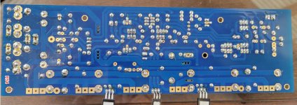
It looks like you could use a hotter soldering iron. Lots of cold joints on that board.

For soldering (SnPb) everything except semiconductors set iron temperature to about 390-400 deg C, for semiconductors 370-390 deg C. That's what I do when using fine tips.
Use the largest tip you can get away with for better heat-transfer too - very fine points are rarely needed unless soldering individual wires to SMT chips (which can be avoided by using reflow oven, again recommended!)
[ Of course I realize that one person's fine point is another's large point! ]
[ Of course I realize that one person's fine point is another's large point! ]
Nope, I agree with you Mark, a large chunk of hot iron, on and off fast. You actually transfer less heat to the device than sitting there for a long time waiting for it to flow.
I have used a Hakko FX-100 soldering iron with a black tip at 750 degrees F for almost all of my builds. That seems to have work out ok, though maybe I got lazy with my technique. On and off fast is my goal.
You need to keep the heat on long enough for the solder to flow out. It should be flat and smooth when you are done. If it's lumpy or balled up it's either dirty or not hot enough, causing a flakey connection.
I recall that I had some feedback that my solder amount was on the heavy side. These last 2 boards I've perhaps gone too light. I will reheat my work.
The entire pad should be covered, most of these are not. If the solder is flowing properly it will cover the entire pad.
Last edited:
Hello Forum Members,
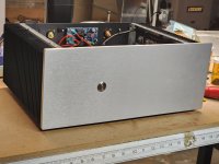
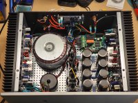
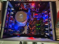
I am happy to report that another Honey Badger has been born! I hit the power switch this morning and felt greatly relieved that everything seemed to power up as expected.
I would like to thank @poseidonsvoice, @jwilhelm, and @Chiptech for their suggestions and technical expertise. For me, it's always a team effort.
DC offset at the speaker outputs wandered slightly, but in general stayed below 1.0 mV DC on the left channel and 0.5 mV DC on the right channel. Several minutes of music with a FiiO digital music player confirmed that it actually plays music. The amp was fairly quiet considering the many concerns I had about decisions made during the build.
The large transformer and even larger V3 diy Audio universal power supply used most of the space available. I had a beautiful satin black transformer cover that I wanted to install but I literally could not make it fit. I briefly mounted the PSU to the front panel to free up space, but couldn't get comfortable with the idea of the power capacitors laying horizontally.
My compromise in the spirit of PSU placement and wire dressing was to keep all mains wiring in the center of the amp. The rail and speaker wiring was routed along the lower outside edges, and the signal inputs along the top rear of the amp.
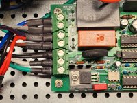
Improvements on the build over my previous build include remote on/off soft start board, the use of wire ferrules and liberal use of shrink wrap to protect wiring.
This is a long post, but the build itself took 4 months so I thought it was worth sharing. I've included some pics of my new Honey Badger.
Respectfully, -Dave M.
I am happy to report that another Honey Badger has been born! I hit the power switch this morning and felt greatly relieved that everything seemed to power up as expected.
I would like to thank @poseidonsvoice, @jwilhelm, and @Chiptech for their suggestions and technical expertise. For me, it's always a team effort.
DC offset at the speaker outputs wandered slightly, but in general stayed below 1.0 mV DC on the left channel and 0.5 mV DC on the right channel. Several minutes of music with a FiiO digital music player confirmed that it actually plays music. The amp was fairly quiet considering the many concerns I had about decisions made during the build.
The large transformer and even larger V3 diy Audio universal power supply used most of the space available. I had a beautiful satin black transformer cover that I wanted to install but I literally could not make it fit. I briefly mounted the PSU to the front panel to free up space, but couldn't get comfortable with the idea of the power capacitors laying horizontally.
My compromise in the spirit of PSU placement and wire dressing was to keep all mains wiring in the center of the amp. The rail and speaker wiring was routed along the lower outside edges, and the signal inputs along the top rear of the amp.
Improvements on the build over my previous build include remote on/off soft start board, the use of wire ferrules and liberal use of shrink wrap to protect wiring.
This is a long post, but the build itself took 4 months so I thought it was worth sharing. I've included some pics of my new Honey Badger.
Respectfully, -Dave M.
Attachments
That looks really nice, Dave. Can I ask what transformer you ended up using? You may have posted that info already, but I couldn't find it right off.
When you have some time listening to it in your main rig, please compare/contrast with the FH9HVX you built a while back. That would be a worthwhile read! Congratulations!
Best,
Anand.
Best,
Anand.
Hi ThNozzleman,
The transformer is an Avel Lindberg 625 vac with dual 45v secondaries. Funny you should ask, because I've had this transformer laying around for years, it was from a failed project several years ago. That was a build I attempted before I discovered the diy Audio community.
I actually chose the Honey Badger as a project so I could make use of this transformer. It's not the recommended 800 vac but a forum member advised me that it would work if I stuck to 8 ohm speakers. Bottom line, it's not the proper transformer for this amp, but I can get by if I watch my speaker impedence.
Thank you for your interest.
Dave M.
Attachments
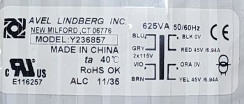
It looks like your amp came together nicely! The volume control is the biggest factor in using a slightly undersized transformer.
- Home
- Amplifiers
- Solid State
- diyAB Amp The "Honey Badger" build thread