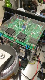
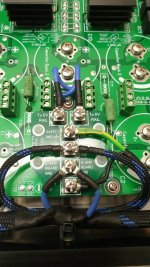
how did you measure?
I calculated it but I don't know if it is correct.
I calculated it but I don't know if it is correct.
if you can do actual measurements of dc power input to your actual amplifier versus the ac power output to a dummy load at the onset of clipping, you will know for sure...
Watch the safe operating area if you do that as this amplifier only has 3 output pairsif you can do actual measurements of dc power input to your actual amplifier versus the ac power output to a dummy load at the onset of clipping, you will know for sure...
Watch the safe operating area if you do that as this amplifier only has 3 output pairs
efficiency is lowest at 1/3 power, so you can test the amp at that level too, then at 80% of full power if you are iffy about full power testing...
That's Great Jeff! 😎It's a good idea to reform caps that have been sitting around for a while.
We've added some optional bells and whistles to the 21'st century protection system. It can now interface with a front panel display and IR remote control.
I hope that will be available soon!
Basically I wanted to calculate the required heat sink thermal resistance but I guess I'll just stick to the recommended 4U chassis because I can get it for half the price where I live.
I am thinking of printing a plexiglass and using it as a front panel. Has anyone ever done that? Is it possible to leave some rectangles unprinted in order to create transparent windows and glue vu meters on the other side of the plexiglass? Also, what do you think is the most stylish mains switch for a power amp?
I am thinking of printing a plexiglass and using it as a front panel. Has anyone ever done that? Is it possible to leave some rectangles unprinted in order to create transparent windows and glue vu meters on the other side of the plexiglass? Also, what do you think is the most stylish mains switch for a power amp?
Basically I wanted to calculate the required heat sink thermal resistance
I'll work it out for you. What max power are you looking at running.
I'll work it out for you. What max power are you looking at running.
The rated max power which is 150w @ 8 Ω.
Ok. To work this out for you it's quite easy. The thing is, I need more information to work it out.The rated max power which is 150w @ 8 Ω.
Q1. What is the ambient temperature that you are typically running the Amplifier in?
Q2. The maximum temperature that the output transistors can run at is 150°C Obviously the closer to the maximum temperature you run the transistor at the more chance of it failing. So what is the maximum temperature that you are happy to run the transistor at when it's operating at full power.
Q3. What are you planning to use as a insulator between the heatsink and the transistors case. A mica pad and thermal paste or something else?
Once I know that I can tell you the required thermal resistance.
The rated max power which is 150w @ 8 Ω.
Looks like you need a Headsink with a thermal resistance of
0.3 °C/W or less.
See Attached
Attachments
Looks like I forgot to de-rate the transistor first.
Please see the updated excel sheet attached
Looks like its going to be fairly hard to run this amplifier at a continuous
150 Watt RMS output into 8 ohms (sine wave) unless you have quite a considerable heat-sink.
Please see the updated excel sheet attached
Looks like its going to be fairly hard to run this amplifier at a continuous
150 Watt RMS output into 8 ohms (sine wave) unless you have quite a considerable heat-sink.
Attachments
Ok. To work this out for you it's quite easy. The thing is, I need more information to work it out.
Q1. What is the ambient temperature that you are typically running the Amplifier in?
Q2. The maximum temperature that the output transistors can run at is 150°C Obviously the closer to the maximum temperature you run the transistor at the more chance of it failing. So what is the maximum temperature that you are happy to run the transistor at when it's operating at full power.
Q3. What are you planning to use as a insulator between the heatsink and the transistors case. A mica pad and thermal paste or something else?
Once I know that I can tell you the required thermal resistance.
Tamb = 20oC
Tmax < 100
Insulator = mica
But its ok because I have decided to use the recommended 4U "dissipante" chassis from hifi2000.
Ok. Just as a note to yourself and others. Your rail voltage will affect the calculation. So for example. In the spreadsheet I was using a rail voltage of 65 volts and adjust the input voltage to get 150 watts output.Tamb = 20oC
Tmax < 100
Insulator = mica
But its ok because I have decided to use the recommended 4U "dissipante" chassis from hifi2000.
However a rail voltage of 60v will also get you an output of 150 watts and due to the lower rail voltage the voltage drop across the transistor will be lower which means the power dissipation will be lower to.
Enjoy.
Hi All 
Long time listener, first time caller here. Based in Melbourne, Australia.
I have finally started building my V2.4 HB boards that I purchased over 3 years ago! I have nearly completed all soldering on the amplifier boards as well as the soft start board. All parts are as per the latest BOM.
I am now working on the parts for the PSU (Im using the V# PSU Board) this is where I am getting a little stuck.... any help here is appreciated!
Firstly I am planning to use standalone bridge rectifiers instead of the Diode board to save on space and parts, from what I understand this Digikey part should be OK? https://www.digikey.com.au/product-detail/en/GBPC3502-E4%2f51/GBPC3502-E4%2f51GI-ND/754833
2. 2 x 45V 800VA transformers seem to be super expensive down here for some reason (RS Components)... Almost double the price of a 2 x 50V 800VA unit. Would the 2 x 50V trafo be suitable?
3. If the 2 x 50V 800VA trafo is suitable, by my calculation I would need to upgrade the PSU caps to 100V instead of the 80V I would have run with the 45V secondarys. Does this sound correct?
4. How much affect does the VA rating have? If I stick with the 2 x 45V but go down to 625VA the price of the trafo is OK and I could run the cheaper 10000uF 80V caps..
I hope this makes some sense! Thanks a bunch in advance!
Hi All
Long time listener, first time caller here. Based in Melbourne, Australia.
I have finally started building my V2.4 HB boards that I purchased over 3 years ago! I have nearly completed all soldering on the amplifier boards as well as the soft start board. All parts are as per the latest BOM.
I am now working on the parts for the PSU (Im using the V# PSU Board) this is where I am getting a little stuck.... any help here is appreciated!
Firstly I am planning to use standalone bridge rectifiers instead of the Diode board to save on space and parts, from what I understand this Digikey part should be OK? https://www.digikey.com.au/product-detail/en/GBPC3502-E4%2f51/GBPC3502-E4%2f51GI-ND/754833
2. 2 x 45V 800VA transformers seem to be super expensive down here for some reason (RS Components)... Almost double the price of a 2 x 50V 800VA unit. Would the 2 x 50V trafo be suitable?
3. If the 2 x 50V 800VA trafo is suitable, by my calculation I would need to upgrade the PSU caps to 100V instead of the 80V I would have run with the 45V secondarys. Does this sound correct?
4. How much affect does the VA rating have? If I stick with the 2 x 45V but go down to 625VA the price of the trafo is OK and I could run the cheaper 10000uF 80V caps..
I hope this makes some sense! Thanks a bunch in advance!
What is it with us Aussies building these amps all at once? 🙂
That bridge rectifier I'm sure would be just fine (corrected link here) but you could find a cheaper one that's just as good - there's an ON and GeneSiC part suggested toward the bottom of the page. I bought GeneSiC parts for the HBs I've just built.
As for the secondary voltage, 50V secondaries would give you around 70V P-P on your supply rails. Enough for a whole lotta power but you'd probably want to be considering some component changes in the amp to cope with it, particularly considering your intended speaker load. Have you built the amps with the recommended output devices?
Haha there must be something in the air!
Yes, I do have the recommended BOM output devices (NJW0281/NJW0302) though they haven't been soldered in yet. They look to have a max power of 150W so perhaps the 50V secondarys aren't a great idea...? I can only assume this as I don't know how to work out how much power they will actually need.
Perhaps if max power is the goal the MJL4281A / MJL4302A (rated to 230W) is the go? Pretty pricey though!
If I do go down this route (50V secondary) the PSU caps will need to be 100V too correct?
Im currently running a pair of fairly efficient 8ohm speakers but im planning to build myself a new set that will be running 4ohm in the future..
Cheers in advance!
Im currently running a pair of fairly efficient 8ohm speakers but im planning to build myself a new set that will be running 4ohm in the future..
It has been recommended to by more experienced builders here to use lower secondary voltages (35V-40V secondaries for 4 ohm loads I believe).
I am using 45V secondaries for an "easy to drive" 6 ohm speaker.
Does anyone know if I can use RN55 (or CMF55 Industrial) vishay dale resistors for every 1/4w and 1/2w value? I am sure for the 1/4w because they are rated at 0.25w@125°C but they are also rated at 0.5w@70°C. What do you think?
Hi All
Long time listener, first time caller here. Based in Melbourne, Australia.
I have finally started building my V2.4 HB boards that I purchased over 3 years ago! I have nearly completed all soldering on the amplifier boards as well as the soft start board. All parts are as per the latest BOM.
I am now working on the parts for the PSU (Im using the V# PSU Board) this is where I am getting a little stuck.... any help here is appreciated!
Firstly I am planning to use standalone bridge rectifiers instead of the Diode board to save on space and parts, from what I understand this Digikey part should be OK? https://www.digikey.com.au/product-detail/en/GBPC3502-E4%2f51/GBPC3502-E4%2f51GI-ND/754833
2. 2 x 45V 800VA transformers seem to be super expensive down here for some reason (RS Components)... Almost double the price of a 2 x 50V 800VA unit. Would the 2 x 50V trafo be suitable?
3. If the 2 x 50V 800VA trafo is suitable, by my calculation I would need to upgrade the PSU caps to 100V instead of the 80V I would have run with the 45V secondarys. Does this sound correct?
4. How much affect does the VA rating have? If I stick with the 2 x 45V but go down to 625VA the price of the trafo is OK and I could run the cheaper 10000uF 80V caps..
I hope this makes some sense! Thanks a bunch in advance!
element14 has 2x40V to 2x55V 625VA Vigortronics toroids for $107 GST included. You need to back order these but multicomp are available but $50 or so more expensive. Primary is 230V (2x115V) so you get 4% higher rails.
Best and not too expensive output devices are njw1302 / 3281, have better SOA than mjl4xxx series at half the price.
cheers,
- Home
- Amplifiers
- Solid State
- diyAB Amp The "Honey Badger" build thread
