In the build guide, at the end, the biasing talks about going with 100mA if the heatsinks are sized correctly. Is this the same as what is referred to as 'running in class A' before switching to class AB. How many watts is this ? My power supply is 0-40@12.5 amps ~ 1KVa, think that works out to 56-0-56 DC.
Are you using two pairs, or three, pairs of output devices?
100mA of output bias in a push-pull output stage results in almost 200mApk of ClassA output current.
2pr gives 400mApk of ClassA
3pr gives 600mApk of ClassA
100mA of output bias in a push-pull output stage results in almost 200mApk of ClassA output current.
2pr gives 400mApk of ClassA
3pr gives 600mApk of ClassA
I'll be using 3 pairs, basically populate the board fully. How does 600mApk translate to Watts ?
Thanks Andrew. Is this math right.
Not considering peak and three pairs of devices:
P=IV /0.300 x 56 = 16.8W
I can't figure how many ohms that power would be at ?
Not considering peak and three pairs of devices:
P=IV /0.300 x 56 = 16.8W
I can't figure how many ohms that power would be at ?
if your I=0.3A and your V=56volts then the power is 16.9W
The resistance would need to be V/R = 56/0.3 = 186r7
The resistance would need to be V/R = 56/0.3 = 186r7
for DC, P=Idc^2*Rload usually written as I²R
For AC you must convert to rms currents and rms voltages.
For a sinewave where Ipk = sqrt(2)*Iac and Vpk = sqrt(2)*Vac, you can use Ipk or Vpk and just include the extra sqrt(2)² term which is divide by 2.
What is the 0.3A that you have used?
For AC you must convert to rms currents and rms voltages.
For a sinewave where Ipk = sqrt(2)*Iac and Vpk = sqrt(2)*Vac, you can use Ipk or Vpk and just include the extra sqrt(2)² term which is divide by 2.
What is the 0.3A that you have used?
Sorry don't understand. I used 0.3A, since a pair of devices gives average of 100mA. Three pairs is 300mA. The voltage used is from a 0-40AC --> 56VDC.
Is that incorrect ?
Is that incorrect ?
incorrect.
The ClassA maximum current is just less than twice the output stage bias current.
If you have 100mA of bias current through each of a 3pair output stage then the maximum ClassA current is just under 600mApk
The maximum ClassA power would be 0.6Apk² * Rload / 2 = 1.44W into an 8r0 test load.
This all falls apart when the load is reactive as in a real speaker.
One does not know the maximum current into a complex reactive load. One can measure actual currents into actual speakers and from that determine roughly what extra current a speaker demands compared to the nominally equivalent resistive test load.
The maximum ClassAB power is Vpk² / Rload / 2
This is determined by measuring the unclipped sinewave Vpk into the test load. This can be simulated by allowing for PSU voltage sag and the amplifier Vloss to arrive at a predicted Vpk from a known quiescent voltage, when no load current is passing.
Last edited:
Ok, that makes sense.
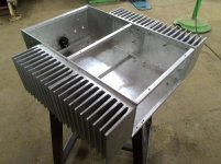
My heatsinks are 3" x 5" x 12". Can we set it higher than the 100mA recommended ? Does it make sense to do this ?
My heatsinks are 3" x 5" x 12". Can we set it higher than the 100mA recommended ? Does it make sense to do this ?
Attachments
Last edited:
the heatsink looks like they are split in two 6" sections. Ensure that both sections receive a heat load and try to get an equal heat load to both and as close to the ends as your device layout will allow.
Try measuring temperatures after you have it running.
Try measuring temperatures after you have it running.
Yes, they are in two parts. The cabinet maker did a good job of the two sections.
I'm a fair way from firing up the output transistors, collecting notes etc...
I'm a fair way from firing up the output transistors, collecting notes etc...
Ok, that makes sense.
My heatsinks are 3" x 5" x 12". Can we set it higher than the 100mA recommended ? Does it make sense to do this ?
Class AB is what it is. Set at @ 20mv across one of your Re's for ON semi.
(or 40mv - tp1 / tp2)
I can go a bit lower on my sankens (<15mv).
NJW0281/0302's , I always run closer to 20mv.
Sanken/ON have a different manufacturing process. But , both work fine
in any of my AB designs.
OS
Andrew and Pete - Thank you.
My build is a fair way from the bias setup. Will post results as the build progresses.
My build is a fair way from the bias setup. Will post results as the build progresses.
Hello Ostripper and other qualified readers.
My speakers have really low impedanse at some frequensies.
Down to 1,6ohm. ( Infinity Kappa 8, for those who need to know)
What is HB's lovest recomended impedande?
Knut Runar
My speakers have really low impedanse at some frequensies.
Down to 1,6ohm. ( Infinity Kappa 8, for those who need to know)
What is HB's lovest recomended impedande?
Knut Runar
Hello Ostripper and other qualified readers.
My speakers have really low impedanse at some frequensies.
Down to 1,6ohm. ( Infinity Kappa 8, for those who need to know)
What is HB's lovest recomended impedande?
Knut Runar
Semelab outputs (maybe sanken mt-200) and <50V rails and it
just might be a good 2R amp.
Standard HB can drive 4R with 60V rails.
OS
honey badger build no. 2 fitting the parts.....
An externally hosted image should be here but it was not working when we last tested it.
Any recommendations for 12VDC power source for HB?
Hopefully this hasn't been answerd already. Please forgive me if so.
If one wanted to use the 12VDC on a boat system for HB amp power, anyone have a suggestion as what one might use as the power supply? Would like to get one capable of the 60V rails needed for the HB.
Thanks all,
Wendell
Hopefully this hasn't been answerd already. Please forgive me if so.
If one wanted to use the 12VDC on a boat system for HB amp power, anyone have a suggestion as what one might use as the power supply? Would like to get one capable of the 60V rails needed for the HB.
Thanks all,
Wendell
An externally hosted image should be here but it was not working when we last tested it.
An externally hosted image should be here but it was not working when we last tested it.
An externally hosted image should be here but it was not working when we last tested it.
- Home
- Amplifiers
- Solid State
- diyAB Amp The "Honey Badger" build thread