ok.
1. One adjusts how much power the amp has with the rail voltage How low can I go.
2. what does the bias really do?
3. Is the slowstart from the audiostore ok as softstart module?
4. do I really need dc protection and does the dc protection really affect audio quality?
5. is the badger much better in monoblock instead of stereo?
;D there I think we have for starters, 😀
I just returned to civilization ...
1. You could get away with 35V rails , but have a <60W amp. 60V rails
are ideal , but the badger will work fine down to 30V (CCS based IPS).
2. Bias smooths the transition at 0 volt where current is equally handled
by the P and N output devices. < +/- 2v , both P/N are conducting (below 1).
Larger voltages are class B , more efficient than class A.
Negative feedback "cleans up" any non-linearity at the 0V point.
3. Same as most soft starts - good enough.
4.The DC protection's sensing circuit has no effect on SQ at all. The
associated relay might ... if it is low quality or defective. I use
50 amp FET solid state ones with .05 ohms on resistance - no audio
quality issues at all.
5. The Badger is one of the better PSRR (ripple rejection) designs.
I doubt whether you could hear much difference between dual mono
or a single power supply.
OS
Attachments
Hi Ost.
thanks for these explainations, helps me make some decissions.
for nr.2; Coming from class a amps, i'm used to always having bias turned up so It's alsways carrying, as for class ab I haven't getting close to understanding how this is regulated, so I need to read up on negtive feedback.
Again Thanks!
Hi Ost.
thanks for these explainations, helps me make some decissions.
for nr.2; Coming from class a amps, i'm used to always having bias turned up so It's alsways carrying, as for class ab I haven't getting close to understanding how this is regulated, so I need to read up on negtive feedback.
Again Thanks!
In the Badger the Tc (temperature co-efficient) of the output stage
in negated by doubling the Tc of Q13.
This thermal feedback loop cancels out the output stages Tc with
a little added multiplication.
Electrically , Q13 reduces (shunts) the voltages across Q14/15 bases ...
reducing current as the output devices get hot.
Globally , final Tc is slightly negative - to prevent thermal runaway.
PS - the main negative feedback is separate , has noting to do with
this separate (thermal feedback) circuit.
OS
So I was looking through some posts from older times, in post 54 about size of transformers.
So for now my speakers are 4R, but times may change. Even so... the post states :
Originally Posted by AndrewT View Post
30+30Vac gives ~ +-42Vdc & ~ 70 to 80W into 8r0 and suits 4ohms speaker
35+35Vac gives ~ +-50Vdc & ~ 100 to 110W into 8r0 and suits 4ohm speaker
40+40Vac gives ~ +-59Vdc & ~ 140 to 160W into 8r0 and possibly suits 6ohms speaker
45+45Vac gives ~ +-68Vdc & ~ 190 to 210W into 8r0, does not suit lower impedance speaker.
The smoothing cap voltage ratings are
>=63Vdc suit 30Vac & 35Vac
>=80Vdc suits 45Vac. . .
That outrules a 45+45 as in the build guide I sort of wanted to follow. Come to think of it... Is the buildguide using the printed voltage rating or the meassured without load?
40-0-40Vac is best (56V+ rails).
Have one of mine with 3 pairs like this - real cool.
Upper 60's for rails , the devices run warmer and loose SOA. My 5 pair
is 73V , needs twice the heatsink.
OS
Have one of mine with 3 pairs like this - real cool.
Upper 60's for rails , the devices run warmer and loose SOA. My 5 pair
is 73V , needs twice the heatsink.
OS
Yes I can see than but then what about this 4R speakers then?
Sent from my GT-I9305 using Tapatalk
Sent from my GT-I9305 using Tapatalk
Another grounding question!
Hello all!
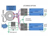
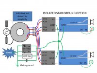
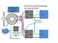
I read Ostripper's post #1430 as well as the ones before it. I also read Rod Elliot's page mentioned in Ostripper's post. But I'm still not clear on how Ostripper is wiring the Wolverine in the photos in post #1430. Specifically Ostripper writes "I'm running everything to a common isolated star point, which I have going to a 35A ground loop breaker." But then he also uses "Litz-braided triplet rails". The photograph appears to show the rails and the "0-volt line" braided and running from the power supply to the amplifier board.
These two techniques seem, to me, to be incompatible. 😕 If the 0-Volt line runs from the power supply directly to the amplifier board, that's not really running everything to a star point, right? Or am I mistaken?
I've included diagrams of what I think the braided triplet rails would look like (diagram #1) and of what I think the star ground would look like (diagram #2). I've also included a third option, in which the 0 Volt line is braided in with the + and - rails for most of the length, but then separates near the power supply, and goes to a star point diagram #3). Can anyone tell me which, if any, of my diagrams is the best way to wire the grounding? I know I'm splitting hairs here, but I really want the -117dB noise floor!
Any help is really greatly appreciated!
Hello all!
I read Ostripper's post #1430 as well as the ones before it. I also read Rod Elliot's page mentioned in Ostripper's post. But I'm still not clear on how Ostripper is wiring the Wolverine in the photos in post #1430. Specifically Ostripper writes "I'm running everything to a common isolated star point, which I have going to a 35A ground loop breaker." But then he also uses "Litz-braided triplet rails". The photograph appears to show the rails and the "0-volt line" braided and running from the power supply to the amplifier board.
These two techniques seem, to me, to be incompatible. 😕 If the 0-Volt line runs from the power supply directly to the amplifier board, that's not really running everything to a star point, right? Or am I mistaken?
I've included diagrams of what I think the braided triplet rails would look like (diagram #1) and of what I think the star ground would look like (diagram #2). I've also included a third option, in which the 0 Volt line is braided in with the + and - rails for most of the length, but then separates near the power supply, and goes to a star point diagram #3). Can anyone tell me which, if any, of my diagrams is the best way to wire the grounding? I know I'm splitting hairs here, but I really want the -117dB noise floor!
Any help is really greatly appreciated!
Attachments
Last edited:
The zero volt line of the supply is the main star ground point. If you are running separate power supplies mono block style, treat them as two separate units completely, then earth ground them together.
Last edited:
The zero volt line of the supply is the main star ground point. If you are running separate power supplies mono block style, treat them as two separate units completely, then earth ground them together.
OK. Thank you for clarifying. But if I'm going to earth ground them together, it sounds like I'm going to need two ground-loop breaker circuits. Is this correct?
Attachments
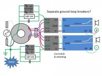
OK. Thank you for clarifying. But if I'm going to earth ground them together, it sounds like I'm going to need two ground-loop breaker circuits. Is this correct?
Dual loop breakers would give you the least chance of getting a ground loop. Tying both together before to loop breaker would leave the amplifier itself properly grounded, but leaves you open for the possibility of a ground loop through the audio signal ground.
You want to maintain one possible path for power to return to ground. If there are two possible paths, any stray noise can induce current flow on ground wiring, which = noise. If both audio signal feed grounds are connected together at the source (pre-amp, cd player, ...), and your star grounds are tied directly together, you have two possible paths.
Last edited:
One MUST complete EACH circuit.These two techniques seem, to me, to be incompatible. If the 0-Volt line runs from the power supply directly to the amplifier board, that's not really running everything to a star point, right? Or am I mistaken?
The connection from transformer to PSU is done via twisted wire pair/s.
The connection from PSU to single polarity PCB is done with a twisted wire pair.
To a dual polarity PCB the connection is via a twisted wire triplet. NOT a litz, nor plaited.
The speaker is connected with a twisted wire pair.
The input is connected with a twisted wire pair.
All these necessary connections must be completed. Post1727, pic middle and pic right are wrong. They break the twisted pairs rule.
Then look at your schematic and tick off all the connections/wires/traces that have been completed properly with these twisted pairs.
Find the FEW remaining connections that are missing.
There may only be a very few, a pair of wires to a remote indicating LED, A pair of wires to an error detection system.
A Signal Return to Power Ground connection via a wire, or trace, or resistor. The Safety connection to protected Chassis.
Select a location on ONE of the existing wire pairs that would make a good and effective Main Audio Ground. It could be the Speaker output terminal, or the Speaker return wire, or the Speaker return terminal on the PCB, or the Power Ground terminal on the amp PCB.
The voltage reference connection from Signal Return to Power Ground can connect to this selected point.
Look at your new point. It will have radial connections from it to other parts of the circuit. It has become a star ground by accident.
It comes LAST. Do the wire pairs FIRST!!!!!!!!
Last edited:
Using a dual secondary transformer converted to a centre tapped with one PSU behaves the same as any centre tapped transformer with one PSU and behaves the same as any centre tapped transformer with two PSUs that are parallel connected and use the centre tap as the Zero Volts.
You need to look at your PSU and identify whether it is a dual bridge rectifier, or a single bridge rectifier (as described above for the CT type).
The dual bridge rectifier type has a separate Zero Volts from any other channels that also have a separate dual bridge rectifier type PSU.
This two channel 4 bridge rectifier assembly (16 separate power diodes) REQUIRES two separate Safety connections to Chassis.
Last edited:
@byroninportland, you still have to twist wires pairs as instructed by andrewt...
this is how actually do my amps...

this is how actually do my amps...
Hello all!
I read Ostripper's post #1430 as well as the ones before it. I also read Rod Elliot's page mentioned in Ostripper's post. But I'm still not clear on how Ostripper is wiring the Wolverine in the photos in post #1430. Specifically Ostripper writes "I'm running everything to a common isolated star point, which I have going to a 35A ground loop breaker." But then he also uses "Litz-braided triplet rails". The photograph appears to show the rails and the "0-volt line" braided and running from the power supply to the amplifier board.
These two techniques seem, to me, to be incompatible. 😕 If the 0-Volt line runs from the power supply directly to the amplifier board, that's not really running everything to a star point, right? Or am I mistaken?
I've included diagrams of what I think the braided triplet rails would look like (diagram #1) and of what I think the star ground would look like (diagram #2). I've also included a third option, in which the 0 Volt line is braided in with the + and - rails for most of the length, but then separates near the power supply, and goes to a star point diagram #3). Can anyone tell me which, if any, of my diagrams is the best way to wire the grounding? I know I'm splitting hairs here, but I really want the -117dB noise floor!
Any help is really greatly appreciated!
I've been using the left pix (post 1727) since last January. Very silent.
The floating ground (before the loop breaker) can read a few mV's.
I also have my heatsinks going right to earth (after the breaker).
PS - my braids shielding also goes direct to earth.
OS
Last edited:
OK! So many valuable responses!
Thank you jwilhelm, AndrewT, AJT and Ostripper for your advice. And everyone seems to be in agreement, or at least are not contradicting each other. The minor difference is that Ostripper likes to braid his triplet rails, while Andrew would twist his. I'm sure they'll both work well as I'm planning on shielding them as Ostripper does.
I'm using two separate dual bridge rectifiers (16 diodes). I'll use the diagram in my post #1729, which I believe satisfies everyone's recommendations.
Then connect the shield at both ends to the Chassis and use a very low impedance connection.
A clamp over the exposed shield that clamps the shield to the chassis is about as low as you can get. Pigtails don't work if they are long.
A clamp over the exposed shield that clamps the shield to the chassis is about as low as you can get. Pigtails don't work if they are long.
twsting and braiding is what Ostripper do....
braidng can be taken from discarded pc monitors' video cables...
but in my case i will connect just one end of the braiding to the circuit ground
with the other end left hanging, since that braid will never cary current...
it serves as electrostatc sheilds...
braidng can be taken from discarded pc monitors' video cables...
but in my case i will connect just one end of the braiding to the circuit ground
with the other end left hanging, since that braid will never cary current...
it serves as electrostatc sheilds...
Doesn't that leave you susceptible to current flow on your shield being it's so close to a large transformer? We do the opposite with interconnect cables.
- Home
- Amplifiers
- Solid State
- diyAB Amp The "Honey Badger" build thread