i have worked in the oil and gas industry for about 15 years,
it is a practice to just earth the shileds at only one end,
during the construction phase, it is agreed opun whre the earthing is done,
at the switchgear side or at the load side...
i a typcal 5 wire 3phase system, the 3 cores are for phases, the fourht
smaller wire is for nuetral and the 5th wire for ground runs....
and there is a reason for this, jwilhelm said it at his above post...
if andrewt wants to earth it at both ends, who am i to stop him? 😉
The practice I'm used to from oil and gas installations here in Norway is that we ground the shield in one end for instrument cables. On power cables we use the shield as ground wire and terminate it in both ends.
that depended on the cables and the design, where metal cable glands were used,
then the wire braiding will ge grounded at both ends, and that is by design...
then the wire braiding will ge grounded at both ends, and that is by design...
The practice I'm used to from oil and gas installations here in Norway is that we ground the shield in one end for instrument cables. On power cables we use the shield as ground wire and terminate it in both ends.
That would leave one path for current flow so no loop would be present, so it wouldn't be an issue. Having a large ground braid connected to two points of a chassis is two very low resistance current paths forming a loop. In normal grounding this would be incorrect. I'm not sure about power wire shielding though.
The shield does not carry signal current.
The shield can pass interference current to Chassis.
H.Ott explains this.
The shield can pass interference current to Chassis.
H.Ott explains this.
Andrew, there is a chance to see a quick picture of your gnd schematic?
I'll be very gratefull.
I'll be very gratefull.
I don't use the general word ground.
Every Flow has a Return.
That Return usually has a specific unambiguous name.
So I connect all these Returns alongside, or twisted with, their respective Flows.
Every Flow has a Return.
That Return usually has a specific unambiguous name.
So I connect all these Returns alongside, or twisted with, their respective Flows.
shield
do you mean the shield of the signal cable connected one end to the amplifier chassis and the other end to the pre or dac or....chassis?
Then connect the shield at both ends to the Chassis and use a very low impedance connection.
A clamp over the exposed shield that clamps the shield to the chassis is about as low as you can get. Pigtails don't work if they are long.
do you mean the shield of the signal cable connected one end to the amplifier chassis and the other end to the pre or dac or....chassis?
both ends of the shield to the Chassis.
For clarity, you are speaking of using a shielded cable that has two wires and a shield.
The shield/screen is the interference suppression.
Not a dual purpose signal and screen.
The signal wires are inside the shield/screen.
Did you read that differently?
Not a dual purpose signal and screen.
The signal wires are inside the shield/screen.
I've been using the left pix (post 1727) since last January. Very silent.
The floating ground (before the loop breaker) can read a few mV's.
I also have my heatsinks going right to earth (after the breaker).
PS - my braids shielding also goes direct to earth.
OS
OK! So many valuable responses!
Thank you jwilhelm, AndrewT, AJT and Ostripper for your advice. And everyone seems to be in agreement, or at least are not contradicting each other. The minor difference is that Ostripper likes to braid his triplet rails, while Andrew would twist his. I'm sure they'll both work well as I'm planning on shielding them as Ostripper does.
I'm using two separate dual bridge rectifiers (16 diodes). I'll use the diagram in my post #1729, which I believe satisfies everyone's recommendations.
These original posts meant to me that the screen is quite separate from the signal wires.Then connect the shield at both ends to the Chassis and use a very low impedance connection.
A clamp over the exposed shield that clamps the shield to the chassis is about as low as you can get. Pigtails don't work if they are long.
Did you read that differently?
Last edited:
The screen we were talking about was shielding the rail power triplet from the supply to the amplifier.
Yes, that's the way I read it as well.
The signal is completely separate from the function of screening interference.
Not a dual duty screen and signal.
The signal is completely separate from the function of screening interference.
Not a dual duty screen and signal.
Hi guys, I'm in the process of building my own guitar amp with the Honey Badger board. Knowing that I will connect in parallel two high quality 8 ohm guitar speaker of 50W each into a mono channel configuration which is gonna give me a total power of 100W with an impedance of 4 ohm. Since I don't want to run at a higher amp output power than the rating of the speakers. My question is will the Honey Badger handle 28.3Vrail instead of +60Vrail? If so which components do I need to replace to make it work?
Thank you!
Thank you!
turn the gain down.
If a short term transient comes along then the amp does not clip and the speaker handles the peak without damage.
It is the longer term that develops significant heat.
If a short term transient comes along then the amp does not clip and the speaker handles the peak without damage.
It is the longer term that develops significant heat.
495-1148-ND 0.1uf film capacitator is not produced any more and is getting harder to get a hold on. Alternatives from farnell and mouser is the B32529C1104J189. It is smaller but readily available. 5mm pin spacing and doesn't fit very well on the card.
These two fits better more or less
B32520C3104J and 871-B32521C1104K289.
Any recommendations?
These two fits better more or less
B32520C3104J and 871-B32521C1104K289.
Any recommendations?
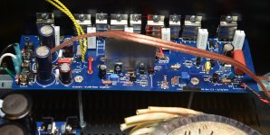
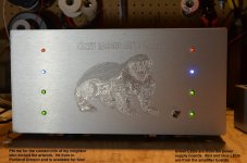
I’d like to share with everyone my latest completed project: the honeybadger!!!
I actually started this project about 3 years ago. In the intervening years I lost a job, moved across the country and started a whole new career. So there were some interruptions.
My build has the following features:
Feel free to contact me with any questions about my build. I'd love to chat about it or help out any one else!
I actually started this project about 3 years ago. In the intervening years I lost a job, moved across the country and started a whole new career. So there were some interruptions.
My build has the following features:
- · Two Honeybadger amplifier boards for stereo.
- · Two diyAudio power supply boards, V1.0 (no longer available)
- · One 800 VA Torroidal transformer with 35V secondaries for +/- 50V rails
- · diyAudio SoftStart, V1.0 (no longer available)
- · Standard 5U chassis from the diyAudio store
- · Two ground-loop isolation units as described in Rod Elliot’s article Earthing (Grounding) Your Hi-Fi - Tricks and Techniques
- · Some rockin’ artwork by my neighbor, Rick. Rick is available for custom artwork like this. He lives near Portland OR. PM me for his contact info.
Feel free to contact me with any questions about my build. I'd love to chat about it or help out any one else!
Attachments
-
 Honeybadger top.jpg499.2 KB · Views: 612
 -
 Honeybadger board.jpg315 KB · Views: 594
 -
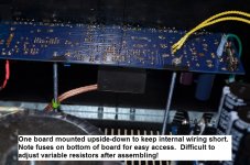 Honeybadger upsidedown board.jpg258.2 KB · Views: 571
 -
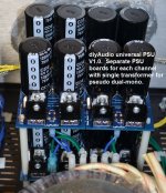 PSU.jpg307.4 KB · Views: 572
 -
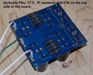 diyAudio PSU bottom.jpg205.2 KB · Views: 567
 -
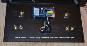 Honeybadger back panel.jpg340 KB · Views: 363
 -
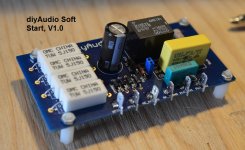 diyAudio SoftStart.jpg197.1 KB · Views: 384
 -
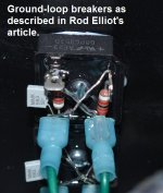 ground loop breakers.jpg121.9 KB · Views: 391
 -
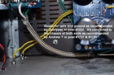 voltage rails shielding.jpg238.3 KB · Views: 365
 -
 Honeybadger front.jpg347.1 KB · Views: 404
Last edited:
- Home
- Amplifiers
- Solid State
- diyAB Amp The "Honey Badger" build thread