Some say the wires to the speaker terminals have to be twisted, hence both connected to the board, to minimize the inductive loop in order to decrease THD. Another thing that I didn't verify yet.
Best regards!
Best regards!
Okay, nice to know. Thank you.
Now something different.
I have toroidal transformer from which I do not know if I can center tap it.
I bought it from an fellow Honey Badger Builder, who probably recovered it from somewhere.
There is no schematic on it and no clear reference. I have 4 secondary wires from which each time 2 form a pair that has a voltage of 35V.
How can I find which wires can be connected to create a center tap?
This is vey important, when I get this wrong I have the possibility of blowing my large capacitors.
How I would do it , take a wire of 1m create a new winding the same winding order as the second 35V one . Let us say you have 5 Vac of less connect to the other 35 Vac , when it adds up you know which connection to make .
Or just connect the two 35 Vac windingen together if the housefuse trips you did it wrong .
Or just connect the two 35 Vac windingen together if the housefuse trips you did it wrong .
Last edited:
I have toroidal transformer ... There is no schematic on it ... I have 4 secondary wires from which each time 2 form a pair that has a voltage of 35V.
How can I find which wires can be connected to create a center tap?
The two pairs are two separate secondary windings. The trick is to connect the two windings in series to get a "single" 35-0-35 center tapped 70V secondary. The question is just how to connect the wires...
- Use a DVM/Ohm meter to figure out which wires belong to the same winding.
- Connect both windings in series. Since you don't know the polarity of your secondaries, there is a 50% chance to get the polarity right (or wrong).
- Connect the primary to the wall AC (a fuse is never a bad idea), with nothing connected to the secondary.
- Measure the AC voltage across the ends.
- If you get approximately 70 VAC (35+35), you've got it right.
- If you measure approximately 0 V, try reversing the polarity of one of the windings and you should get the 70 VAC.
Some say the wires to the speaker terminals have to be twisted, hence both connected to the board, to minimize the inductive loop in order to decrease THD. Another thing that I didn't verify yet.
Best regards!
in my own amps, i do not use the board for speaker ground returns, i used the junction of the filter caps directly instead....i may try that in future but for now i am happy with my set up...
The two pairs are two separate secondary windings. The trick is to connect the two windings in series to get a "single" 35-0-35 center tapped 70V secondary. The question is just how to connect the wires...
- Use a DVM/Ohm meter to figure out which wires belong to the same winding.
- Connect both windings in series. Since you don't know the polarity of your secondaries, there is a 50% chance to get the polarity right (or wrong).
- Connect the primary to the wall AC (a fuse is never a bad idea), with nothing connected to the secondary.
- Measure the AC voltage across the ends.
- If you get approximately 70 VAC (35+35), you've got it right.
- If you measure approximately 0 V, try reversing the polarity of one of the windings and you should get the 70 VAC.
all my traffo builds are now 4 wires with no center taps....
i use the two rectifier psu ala Nelson Pass....
Attachments
Hi tony,
With solid state, the speaker returns should go to the junction of the main filter capacitors, but on the quiet side. The transformer returns should be left completely alone. I actually make two links between the filter caps. One has the transformer return(s) centred, the other goes off to various circuits and speaker returns. That way the quiet side and noisy side are enforced.
With tube amps, the cathoses go to the capacitor that feeds the output transformers. The common point for the actual speaker output goes to the quiet ground and is treated exactly like the input signal common.
-Chris
Hi tony,
With solid state, the speaker returns should go to the junction of the main filter capacitors, but on the quiet side. The transformer returns should be left completely alone. I actually make two links between the filter caps. One has the transformer return(s) centred, the other goes off to various circuits and speaker returns. That way the quiet side and noisy side are enforced.
With tube amps, the cathoses go to the capacitor that feeds the output transformers. The common point for the actual speaker output goes to the quiet ground and is treated exactly like the input signal common.
-Chris
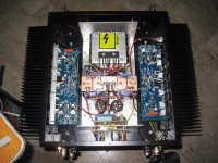
Hi Chris, as you can see in my picture, i used the Nelson Pass dual rectifier bridge configuration so that the transformer center tap, there being none need not connect to any filter cap junctions...in this way, there is galvanic isolation between the traffo secondary and the psu filter caps...
in all my builds, tubes or ss i employ a central grounding network, and it has given me quiet amps so far....
If you use two separate bridge rectifiers, then you can’t get a symmetrical psu of for example +50 and -50V?
Wouldn’t you get +50V and 0V? Or is there a way with two separate rectifiers to still get the symmetrical psu, needed for the amplifier boards?
If you use two separate bridge rectifiers, then you can’t get a symmetrical psu of for example +50 and -50V?
Wouldn’t you get +50V and 0V? Or is there a way with two separate rectifiers to still get the symmetrical psu, needed for the amplifier boards?
With dual rectifiers you are rectifying the output of each output winding of the transformer to DC, then you join the positive output of one rectifier and the negative output of the second rectifier to form your ground. This gives you a symmetrical +/- power supply
Attachments
Last edited:
First thing use diagram 1 and connect primary to mains using a lightbulb as current limiter.
the bulb will only protect the transformer if you make an error and will glow bright in such case.
Then connect secondaries using diagram 2, if you get 70V at voltmeter B-C is your centre tap and you have the 35-0-35 V connection. If you get around 0 volts at voltmeter you must try using diagram 3.
Then connect secondaries using diagram 3, if you get 70V at voltmeter B-D is your centre tap and you have the 35-0-35 V connection. If you still get around 0 volts at voltmeter you must have made an error.
Attachments
@ jwilhlm What advantages do you have using 2 bridge rectifiers? I know that 2 bridges can handle more current then using only one, In this case of this chap having a modest power amplifier and he can use only one bridge Does it make any difference in audio quality?
Regarding symmetry if the windings of the transformer are wound together then the output voltages are also the same, if not with one or 2 bridge rectifiers the voltage difference between the windings will also reflect in the final rectified and smoothed voltage.
Regarding symmetry if the windings of the transformer are wound together then the output voltages are also the same, if not with one or 2 bridge rectifiers the voltage difference between the windings will also reflect in the final rectified and smoothed voltage.
Dual rectifiers help eliminate ground loops. The trade off is a slight decrease in output power. I usually use them in my builds.
Why, how?
I can't remember the exact explanation as to why this is supposed to help, I just tried it in one of my first builds with great results and rolled with it. Here's another explanation from Nelson Pass as to why they are used.
"Most customers want total silence from the amplifier, including
mechanical noise. If there is not complete matching between the
secondary coils and only 1 rectifier bridge, any net DC imbalance
between the current of the + supply and the - will tend to
saturate the core of the transformer and create noise. This is
seen for quite low current differences and can also show up with
low frequency output. Using two bridges eliminates the problem.
In the eyes of a manufacturer, any other subtle differences
pale in comparison to the cost of having to replace a transformer
in the field due to mechanical noise."
^let me try....
the power traffo secondary if wound one on top of another and then joined to form the center tap will have different lengths and dc resistances, now as ac currents as drawn, the terminal voltage will differ unequally and this caused the center tap to wander about albeit small....
the power traffo secondary if wound one on top of another and then joined to form the center tap will have different lengths and dc resistances, now as ac currents as drawn, the terminal voltage will differ unequally and this caused the center tap to wander about albeit small....
^let me try....
the power traffo secondary if wound one on top of another and then joined to form the center tap will have different lengths and dc resistances, now as ac currents as drawn, the terminal voltage will differ unequally and this caused the center tap to wander about albeit small....
...and negligible, I'd say...
Best regards!
I can't remember the exact explanation as to why this is supposed to help, I just tried it in one of my first builds with great results and rolled with it. Here's another explanation from Nelson Pass as to why they are used.
"Most customers want total silence from the amplifier, including
mechanical noise. If there is not complete matching between the
secondary coils and only 1 rectifier bridge, any net DC imbalance
between the current of the + supply and the - will tend to
saturate the core of the transformer and create noise. This is
seen for quite low current differences and can also show up with
low frequency output. Using two bridges eliminates the problem.
In the eyes of a manufacturer, any other subtle differences
pale in comparison to the cost of having to replace a transformer
in the field due to mechanical noise."
I do not think that the trafo has any reason to saturate
1)consider that you load the center tap winding one side with a 100w and the other with 200w what difference does it make regarding saturation of the core? The primary will see a single load of 300 watts that's all.
The return path is isolated by the bridge rectifier.
2) For me center tap wonder will occur mostly to imbalance of the value of the capacitor bank capacitance, ESR etc. after all we are looking at the peak voltage.
3) Looking a bit further how exactly is the gain of each output transistor is matched? some minor differences are always present and nothing is perfect in this world. The load imposed on the PSU is not exactly the same so it seems that one side will load more than the other. The voltage drop on each winding will be a bit different due to this. The center tap will wonder a little because of this.
A regulated supply will eliminate all this but it adds to more complexity of the setup which will hardly be noticeable compared with a non regulated one.
^let me try....
the power traffo secondary if wound one on top of another and then joined to form the center tap will have different lengths and dc resistances, now as ac currents as drawn, the terminal voltage will differ unequally and this caused the center tap to wander about albeit small....
This sounds more familiar to what the original theory I was told behind the dual bridges. When using independent supplies for each channel (dual monoblock) different ground potentials between each supply can set you up for current flow through the audio grounds when using a source with common audio grounds.
I can't remember the exact explanation as to why this is supposed to help, I just tried it in one of my first builds with great results and rolled with it. Here's another explanation from Nelson Pass as to why they are used.
"Most customers want total silence from the amplifier, including
mechanical noise. If there is not complete matching between the
secondary coils and only 1 rectifier bridge, any net DC imbalance
between the current of the + supply and the - will tend to
saturate the core of the transformer and create noise. This is
seen for quite low current differences and can also show up with
low frequency output. Using two bridges eliminates the problem.
In the eyes of a manufacturer, any other subtle differences
pale in comparison to the cost of having to replace a transformer
in the field due to mechanical noise."
Is this claim, or are many other of NP's claims, in keeping with what e.g. Douglas Self said wrt to blameless amplifier designs? Did he substantiate it/them with measurements? Otherwise it is more or less snake oil, I'd say.
Best regards!
- Home
- Amplifiers
- Solid State
- diyAB Amp The "Honey Badger" build thread