Is this claim, or are many other of NP's claims, in keeping with what e.g. Douglas Self said wrt to blameless amplifier designs? Did he substantiate it/them with measurements? Otherwise it is more or less snake oil, I'd say.
Best regards!
This was a quote from the Bob Cordell Interview thread. Bob Cordell Interview: Power Supplies
I doubt Nelson Pass does much of anything according to Doug Self's blameless designs. I think it's a bit of a stretch calling him a snake oil salesman though
I have read NP's documents, and never came across any claims!. everything said is backed by measurements and sound theory.
Do you have any practical experiments that say otherwise?
snake oil? hmm, that's not kind words.
Regards
Prasi
Do you have any practical experiments that say otherwise?
snake oil? hmm, that's not kind words.
Regards
Prasi
...and negligible, I'd say...
Best regards!
unless we can quantify it, i will not dismiss theory that easy...
Hello fellas,
I’m a newbie to the diy community but I’m enjoying the build!
I have a question regarding the ground.
Is the following correct:
The ground of the 230V is connected to the chassis.
The secondary centre wire of the transformer (to get a symmetrical power supply) is also connected to the chassis.
In this case everything form speakers ground to signal ground is connected to the chassis.
Am I right or wrong? I’ve tried to search multiple times in the thread but I can’t seem to find a clear answer to me.
Thank you very much
the ground associated with the power cables is directly connected to the chassis metal work, preferably to one of the bolts holding the IEC inlets, this is for safety reasons....so that the operator do not receive nasty shocks in case of accidents..
the psu grounding or zero returns are another thing, they are not to be confused with mains power grounds...
the psu system can have a central grounding bus where all the return leads are soldered in...
if you are familiar with atx psu's you will see what i mean..
all B+/B- wires should have a corresponding return wires twisted where practical...
you can connect psu ground to the chassis at one point only, suggested at the point where signal levels are lowest...
so what happens if you use a plastic casing like i do often? still the above can be applied...
Is this claim, or are many other of NP's claims, in keeping with what e.g. Douglas Self said wrt to blameless amplifier designs? Did he substantiate it/them with measurements? Otherwise it is more or less snake oil, I'd say.
Best regards!
surely Jim Bonjiorno, creator of the GAS Ampzilla must have seen the merits of using power traffo secondaries that are bifilar wound....it is there in the 1980's Audio Magazine that i first saw this mentioned...
up till then, i was winding my traffos the traditional way, one on top of another...
when i tried bifilar winding, i saw secondary voltages that are exactly identical in terminal voltage, being of the same turns, same length, same dc resistance, what is not to like..? 😀
Btw, on theory: Let's assume we drive the HB, or any other power amplifier, by a 1 kHz squarewave signal with a duty cycle of 9:1 (900 µs on/100 µs off). With separate bridge rectifiers the positive rail wil be charged 90%, the negative one with only 10% of the whole DC load. Same applies for the secondaries. Will we ever notice any inbalance within the transformer? I don't assume so. Otherwise, with a single bridge the load automatically will be balanced well between both windings. So, if we assume any harm by different loading of both secondaries, which also corresponds to different DC resistances (as the 90 % winding sooner or later will get hotter) and hence is applicable, this harm will be egalized automatically by the single bridge rectification.
Best regards and a happy new year!
Best regards and a happy new year!
even so, that same square wave with 90% duty cycle will have a positive peak and a negative through centered around the psu zero volts on a split rail system....after all, the peak to peak waveform is the sum of the rails.....
all i am saying is that if the two traffo secondaries are not exactly equal, then their terminal ac voltages will vary and so the dc rails so that the zero point moves up or down wrt to the rails and that is a distortion...
this is what Jim Bongiorno must have realized...and so the bifilar power traffo...
Antek traffos offers their toroids like this...
Hi All, Happy new year to everybody.
I was just wondering if there is a troubleshooting guide for the honey badger or any other class AB amplifier for that matter available on the web or on the DIY forum somewhere?
I have a friend who is having trouble with his honey badger amp and was just trying to help him out without doing any further damage.
I guess it easy to check that components are installed correctly.
Rail voltages are correct.
Use a current limiting dual rail power supply to help diagnose without letting the smoke out. But what happens after that?
Is it possible to divide the amp up in separate sub circuits "input stage", "Voltage amplifier stage" and "Output Stage" to check these. I have built the HB myself and luckily did not have any troubles. I have also built a few amps on a breadboard and know that due to the high open loop gain which is only placed under control once the negative feedback loop is in place it is a bit hard to just divide up and test the amp.
Maybe someone with a bit more trouble shooting skills can offers some advise.
Regards Stuart
Hello guys,
Thank you very much for the schematics. I now have a symmetrical PSU 🙂
I have another problem who keeps following me, the guy who sold me all the parts has delivered a 35V - 220 uF non polar elco for C4 on the amplifier boards, instead of a 50V-100V one. Is this a serious problem? I’m already waiting more than a month on the replacement but I wonder if it’s worth it?
all i am saying is that if the two traffo secondaries are not exactly equal, then their terminal ac voltages will vary and so the dc rails so that the zero point moves up or down wrt to the rails and that is a distortion...
this is what Jim Bongiorno must have realized...and so the bifilar power traffo...
Antek traffos offers their toroids like this...
Tony,
you're well known as a transformer maker here, hence supposedly should have great experience. So you most probably might tell us whether a bifilarly wound double secondary is more expensive than two separate ones, wound after each other. If not, I'll be asking for bifilars in the future, 'cause it appears to make sense 😉.
Best regards and a happy new year!
Is it possible to divide the amp up in separate sub circuits "input stage", "Voltage amplifier stage" and "Output Stage" to check these.
This is a very good approach to building an amplifier. I always do this.
Assemble everything left of the red line. Install two 100R resistors temporarily connecting the VAS output to the feedback. Where the two red resistors join to the feedback can be used as output for testing.
Measure the voltage from the new temporary output to ground. This should be very close to zero volts. Measure the voltage drop across one of the temporary 100R resistors (either one, doesn't matter). Divide this voltage by 100. This will give you your VAS current. For example if you are aiming for 7mA VAS current (this is a good target) you should read around 0.7VDC across the resistor. You should be able to pass an input signal through the amp now. The temporary output point should be amplifying the signal to full output voltage, but won't have enough current behind it to drive anything yet.
If it doesn't behave like this, fix the issue now before installing any more parts. If it's working properly proceed to assemble the rest of the board.
Attachments

Last edited:
Thank you Jeff that's exactly what I was looking for.
I really appreciate your input. This will certainly help with the diagnosis of the amp.
One more question if you don't mind.
What would be the lowest rail voltage that you think I could test this with as I know that the cascade above the differential pair requires around 15v?
I really appreciate your input. This will certainly help with the diagnosis of the amp.
One more question if you don't mind.
What would be the lowest rail voltage that you think I could test this with as I know that the cascade above the differential pair requires around 15v?
I'm not sure what the minimum voltage the Honeybadger will operate properly at but ideally it should be tested at the target voltage for the power supply, that's what you need to verify it will operate at. You can power the input through current limiting resistors (R53 & R54) if you're worried about damage due to problems but I don't normally bother, input parts are cheap.
Tony,
you're well known as a transformer maker here, hence supposedly should have great experience. So you most probably might tell us whether a bifilarly wound double secondary is more expensive than two separate ones, wound after each other. If not, I'll be asking for bifilars in the future, 'cause it appears to make sense 😉.
Best regards and a happy new year!
my view on such was never the same after 1980, it made sense to me that i will never use such traffo unless it was bifillar wound secondary...i have never looked back since...
Hi All, Happy new year to everybody.
I was just wondering if there is a troubleshooting guide for the honey badger or any other class AB amplifier for that matter available on the web or on the DIY forum somewhere?
I have a friend who is having trouble with his honey badger amp and was just trying to help him out without doing any further damage.
I guess it easy to check that components are installed correctly.
Rail voltages are correct.
Use a current limiting dual rail power supply to help diagnose without letting the smoke out. But what happens after that?
Is it possible to divide the amp up in separate sub circuits "input stage", "Voltage amplifier stage" and "Output Stage" to check these. I have built the HB myself and luckily did not have any troubles. I have also built a few amps on a breadboard and know that due to the high open loop gain which is only placed under control once the negative feedback loop is in place it is a bit hard to just divide up and test the amp.
Maybe someone with a bit more trouble shooting skills can offers some advise.
Regards Stuart
Hi Stuart,
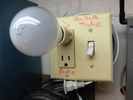
first ,i use a series mains lamp tester, so that mistakes in biasing can be uncovered without serious damage to the output trannies in case of mistakes..
second, there is a low ohm resistors in parallel with the rail fuses, you can power up the amp without the rail fuses at first so that when there is a mistake, these resistors burn out quickly preventing the release of high energy to the output trannies..
third, if there were no mistakes, then the low ohm resistors do not burn out, so that you can now check for output offset voltage, close to zero volts as much as possible, adjust the sore volt pot for this..a few +- milivolts is acceptable..
fourth, you can then adjust for output idle current, you can clip a milli-voltmeter to the fuse clips, say you used 2.2 ohms across the fuse clips, then a reading of around 100 mV tell you the output stage is at around 50 mA, this is by no means accurate but in the ball park...
fifth, if you have a scope, a dummy load and and a signal source set to 1 khz, adjust the input signal so that you get 2.8 volts into your 8 ohm dummy load, this is the 1 watt output level.. look at the scope and check that there is no crossover distortion, adjusting the idle bias to smoothen the sine wave output..btw the rail fuses are inserted before this test is conducted...

sixth, if you do not have the set up called for in fifth, you can listen to the amp at low volume levels and listen that the sound is not distorted...
i do not test my completed amp in stages, i test them as a fully built amp, it there were no mistakes, it will work the first time...
Hi tony,
I build the amp complete, then use the variac to slowly increase the voltages while I watch things like bias and offset. Different amplifiers behave differently of course. One thing I like to do is increase the voltage until I start seeing some bias current. Then I adjust both channels to be the same. Increasing the voltage further I check between the channels and if one channel bias is much higher than the other I'll either look for the problem, or readjust them to be about 1/2 what we want and continue increasing the voltage. Both channels should then stay in the same ballpark. If they don't you have a problem. Turn the voltage down and start looking for it.
I never use a dim bulb tester because the variac allows me to test at known reduced voltage levels. You can do an awful lot of troubleshooting at reduced voltages without any damage to something that might have smoked with a dim bulb tester.
When things go wrong, they often go wrong very quickly. You can slow that process down with a variac which gives you time to act before the air fills with capacitor fluff. Not always, but most of the time. You absolutely must pay attention to everything, and that includes noticing hot smells, smoke or imminent capacitor destruction odours. Listening can really help too (duck when you hear hissing, don't waste time looking around!).
I think where you are able, Jeff's suggestion of testing the voltage amp first has a lot of merit. Use the variac for those tests as well. Don't have a variac? Time to get one!
-Chris
I also have a 3 kva variac, but i never used them to liven up an amp i just built...i used them for "short circuit" testing my built up traffos....to find out copper losses at full load...

the procedure i laid out should not be so difficult to follow.....
those low ohms resistors shunting the rail fuses is a "circuit nuance" incorporated by Ostripper...i knew Ostripper put them there for a reason...
the procedure i laid out should not be so difficult to follow.....
those low ohms resistors shunting the rail fuses is a "circuit nuance" incorporated by Ostripper...i knew Ostripper put them there for a reason...
I'm not sure what the minimum voltage the Honeybadger will operate properly at but ideally it should be tested at the target voltage for the power supply, that's what you need to verify it will operate at. You can power the input through current limiting resistors (R53 & R54) if you're worried about damage due to problems but I don't normally bother, input parts are cheap.
as long as the input cascodes are biased with current to keep it conducting, then the rails can go low, the small and the big CCS keeps the bias to the rest of the amp steady......
i have seen a local build tested at +-15 volts...
Most amps I build these days have plug in input boards. It makes for easy testing of separate stages.
I still like the light bulb for initial power up with the output stage. Very easy to see if things are going bad without needing to watch meters.
I still like the light bulb for initial power up with the output stage. Very easy to see if things are going bad without needing to watch meters.
yes, the only reason fir the output stage burning out is an open biasing networks brought about by stuffing errors and it would be easy to spot it with a dmm to read small dc voltage across the Vbe shunt reg..
- Home
- Amplifiers
- Solid State
- diyAB Amp The "Honey Badger" build thread