Here's the easy way to bend resistor leads neatly. Once you figure out the magic spot on the needle nose pliers, the leads will fit perfect every time.
Sure! I've been doing this since I was a child. 🙂
I used these: LVR05R2200FE12 Vishay/Dale | Mouser
No problems. Sounds awesome.
Does anybody know if he used "flying leads" ? Seems like a not so good idea to me, but my leads can't reach like that!
Attachments
Nothing wrong with bending over the lead nad insulating to help avoid accidents.
The current route up through the device matches the current route down through the lead out and the result is almost no change in inductance compared to using a smaller component.
The current route up through the device matches the current route down through the lead out and the result is almost no change in inductance compared to using a smaller component.
I think his concern is his leads aren't long enough. He would need to splice them above the board.
I think his concern is his leads aren't long enough. He would need to splice them above the board.
Yes, this is the problem. I can bend the leads so the resistors form a "|_|" shape, and tuck the leads under the body approx 1.5 cm, but it looks God awful, lol.

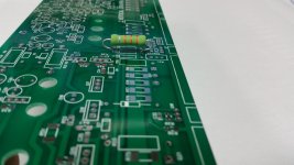
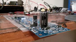
I bend my high power resistors like this. It lifts them away from the board, so the board won't turn brown. You can modify the bends to fit different spacing easily.
Thanks, that's similar to what I tried at first. I'll take a picture after breakfast. I have to choose between interfering with C17, or the OPS leads. Maybe I'll change the OPS orientation to "flat mounted" against the heatsink and just do it that way.
I am slightly worried about the integrity of the leads, as I keep re-shaping them.
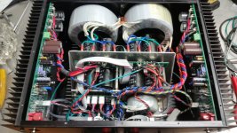
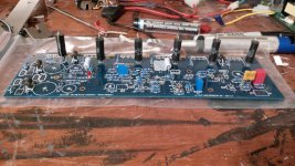
You sure have alot going on in there! lol. That looks like it took alot of planning. Does that small Toroidal power protection? Also, were your Toroid mounting hardware included with your XFMRs?, my XFMR never came with any washer, insulators, bolt, etc.
I try to have the whole amplifier drawn up before I order the PC boards.
I always use Antek transformers. They come with mounting hardware.
The small toriod powers the amp control system.
I always use Antek transformers. They come with mounting hardware.
The small toriod powers the amp control system.
Last edited:
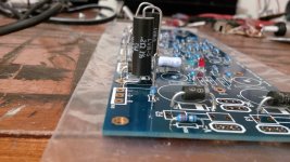
Are those 5 watt parts?
That looks to be the only emitter resistor that does not have clearance towards the middle of the board. Work this one out and the others will be easier.
I almost always mount the pc board flat to the heatsink. Saves space but can make the adjustments hard to reach once the amp is assembled.
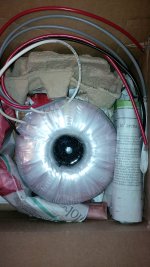
I also use Antek transformers...They are local to me. Do your transformers have the center hole filled with epoxy and drilled for a bolt? That seems nicer the Antek.
That looks to be the only emitter resistor that does not have clearance towards the middle of the board. Work this one out and the others will be easier.
I almost always mount the pc board flat to the heatsink. Saves space but can make the adjustments hard to reach once the amp is assembled.
I also use Antek transformers...They are local to me. Do your transformers have the center hole filled with epoxy and drilled for a bolt? That seems nicer the Antek.
Are those 5 watt parts?
That looks to be the only emitter resistor that does not have clearance towards the middle of the board. Work this one out and the others will be easier.
I almost always mount the pc board flat to the heatsink. Saves space but can make the adjustments hard to reach once the amp is assembled.
I also use Antek transformers...They are local to me. Do your transformers have the center hole filled with epoxy and drilled for a bolt? That seems nicer the Antek.
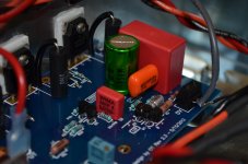
1) Yes, those are Dale 0R2 5W resistors.
2) I agree. I wanted to make the adjustments easier, but I am okay with either orientation. I just wanted to do something a little bit different. 🙂
3) Center hole is filled and drilled, it came from SumR - (Primrose division), it looks great, and used good(expensive) 12 GA wire secondaries, etc. Just never came with the hardware to mount.
Attachments
Last edited:
Okay, I've played around with the 5 Watters. Regardless of the orientation, there are two that would interfere with capacitors on the PCB unless they are mounted close to vertical. Has anyone extended leads before? *I could solder a piece from one end onto the other, I just never seen it done before.
*Making a post that sticks up out of the PCB for the Lead to solder to.
*Making a post that sticks up out of the PCB for the Lead to solder to.
Last edited:
I've extended them several times. What are we talking about? Adding 2mm of wire? Can't be an issue.
I've extended them several times. What are we talking about? Adding 2mm of wire? Can't be an issue.
Thanks! I'll probably add a 1cm "post" so I can make it work and stay visually appealing for myself, lol.
Last edited:
I like the idea, in practice it could have been done cleaner. I forgot to shrink wrap until it was too late. Oh well, live and learn.
I've seen shrink wrap encasing the entire part and its leads for diodes (axial parts mounted vertically). Could you do that here, or is there too much heat?
I've seen shrink wrap encasing the entire part and its leads for diodes (axial parts mounted vertically). Could you do that here, or is there too much heat?
I'm not sure to be honest. 😕
- Home
- Amplifiers
- Solid State
- diyAB Amp The "Honey Badger" build thread