Sorry I feel we exhausted this topic but what is Sprint's default through hole diameter for a 1/4W resistor or did you create the parts manually?
Here is one I just made. Special to get those big flyback diodes (D103/4)
to mesh with my double sided rails.
I dialed in 2mm holes on a 4mm pad .. added diode artwork.
OS
Attachments
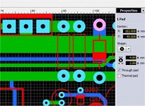
2mm for the MUR420-MUR460 should be more than adequate.
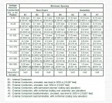
1.3mm(max lead diameter)+.075mm(for board manufacturing tolerance)=1.375mm(min hole size)
1/4W Resistors
.65mm(max lead diameter)+.075mm(for board manufacturing tolerance)=.725mm(min hole size)
PS the board is looking good by the way
1.3mm(max lead diameter)+.075mm(for board manufacturing tolerance)=1.375mm(min hole size)
1/4W Resistors
.65mm(max lead diameter)+.075mm(for board manufacturing tolerance)=.725mm(min hole size)
PS the board is looking good by the way
2mm for the MUR420-MUR460 should be more than adequate.
1.3mm(max lead diameter)+.075mm(for board manufacturing tolerance)=1.375mm(min hole size)
1/4W Resistors
.65mm(max lead diameter)+.075mm(for board manufacturing tolerance)=.725mm(min hole size)
PS the board is looking good by the way
Yep , .8mm for small resistors.
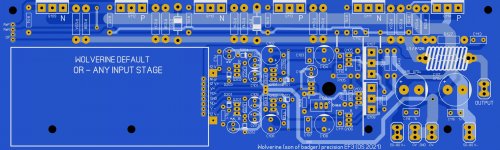
I redid the board. (below) flipped +/- around. Made a mistake. R112/113
go BEFORE the main drivers.
The simulation worked good with these resistors just decoupling the predrivers.
Most likely would not of oscillated. Still , I wanted to go with
the proven Slewmaster way.
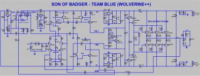
What happens on a EF3 is quite interesting. At low to moderate power
the pre-drivers and drivers have Hfe in the same range. (depending on
device type).
At higher power , the pre-drivers have the most gain .... as the main drivers
"droop" (lose hfe) under load.
So decoupling the pre -drivers stops FB from the rails. Decoupling both
driver/predriver seems to do an even better job.
The OEM's decouple the drivers , as well .... they use higher gain TO-220 drivers.
28uA = 4.5A at output. This EF3 has X 150,000 current gain.
Load does not seem to have any effect. 60+ uA at full 2R load.
Oh , I went all the way with NFB. (below)
It should match the original schema exactly.
OS
Attachments
So R112 and R113 (10ohms) are actually between Outputs and the Drivers and not between the Drivers and Predrivers? When the Driver draws significant current there will be some significant voltage drop across the 10ohm resistors driving low impedance loads if they are between the Drivers and Outputs.
What about 1ohm between the Outputs and Driver stage and 10ohm between the Driver and Predriver? That will require an extra set of bypass/decoupling caps though.
So R112 and R113 (10ohms) are actually between Outputs and the Drivers and not between the Drivers and Predrivers? When the Driver draws significant current there will be some significant voltage drop across the 10ohm resistors driving low impedance loads if they are between the Drivers and Outputs.
At 10R , max 56mA driver load 2R. Not much of a voltage drop. 1.8V at the Q7
collector (58.8V).
At this point the real world PS rails would begin to "fold".
Yep , 10A /2R per rail. Traces are 12.75A.
OS
Is the simulator taking beta droop into account?
Example:
59V÷(2ohm+.22÷3) = 28.46A through the outputs.
28.46A/3 = 9.49A per Output. Beta for the PNP at 9.49A is about 40.
So... 28.46A/40 = .71A peak collector current through the Driver , which is 7.1V across the 10ohm resistor.
Example:
59V÷(2ohm+.22÷3) = 28.46A through the outputs.
28.46A/3 = 9.49A per Output. Beta for the PNP at 9.49A is about 40.
So... 28.46A/40 = .71A peak collector current through the Driver , which is 7.1V across the 10ohm resistor.
Well I guess it depends on how well you want to be able to drive 2ohms.
The 28.46A is the total peak current through the Outputs, the average current will be 9-10A which you sized the traces for.
The 28.46A is the total peak current through the Outputs, the average current will be 9-10A which you sized the traces for.
Device SOA would never allow this. Closest you could get would be 3 pair
Sanken MT-200's running 50V rails.
I don't mean this to be a 2R amp. But , it would be able to handle difficult
speakers with strange impedance dips better than an EF2.
OS
Sanken MT-200's running 50V rails.
I don't mean this to be a 2R amp. But , it would be able to handle difficult
speakers with strange impedance dips better than an EF2.
OS
Ok things are looking a little better.
VAC 40-0-40 800VA transformer will give you these voltages under load for two channels.
8 ohms +/-54V
4 ohms +/-51V
2 ohms +/-45V
So the SOA will be much better but there could be brief periods of time where the outputs will have to survive +/-59V until the supply sags.
I recalculated the voltage drop on the 2ohm sagged voltages and the voltage drop across the 10ohm will be 3.1V.
I would like to investigate stability of the EF3 moving the 10 ohms between the Predrivers and Drivers and adding parasitic inductances to see if it's stable. I can play with that tonight and see what happens.
Jeremy
Last edited:
I checked SOA at 2R. The worst case load could only be 2ohms at 30° reactive at Tc=60°C, so highly reactive loads are out of the question for 2R.
Last edited:
Just to assure people all is being considered .... (below).
I did not know elevation affected creepage.
My minimum is .8mm between rail/ground potential. Between rails 1.5-2mm.
OS
Yep, I sometimes test things at 70,000ft. Interesting things happen like corona discharge (not the virus) in an altitude chamber.
Device SOA would never allow this. Closest you could get would be 3 pair
Sanken MT-200's running 50V rails.
I don't mean this to be a 2R amp. But , it would be able to handle difficult
speakers with strange impedance dips better than an EF2.
OS
I agree, 2R would be a strange impedance dip not a nominal load to be hooked up.
In terms of having the most power out, R112/113 between the Predriver and Driver is better. In terms of EF3 stability it's hard to say which position is better without some bench test so go with what you know works.
What do the OEMs do? Can you give an example so I can check their schematics?
Last edited:
On stability and even the base design (below).
It's locked in now ....
Just the base wolverine , no cascode. Just the proven Slew EF3.
Russle's option of the two pole compensation and the option of
a servo - less amp.
Those options would just entail omitting the 12v supplies/servo and
adding a bipolar capacitor. You then have the original Badger (refined).
Since this board has the Modular option , any tinkering with CFA's or
Cascoded VAS's can be had by omitting the onboard IPS and using
the 8 pin connector (50 X 100mm daughter card).
Such a easy BOM ... despite a few more parts.
PS - later I will show 3-4 examples of OEM EF3 implementation.
OS
Attachments
Last edited:
... by omitting the onboard IPS and using
the 8 pin connector (50 X 100mm daughter card).
I was looking at the last posted PCB revision (post #84), and was wondering about the onboard IPS.
I'd be interested in trying a few inputs once I have a stable system up and running. I'd like to try out the onboard IPS (I'm assuming this will be "hard wired" to the PCB? or perhaps it will also be a daughter board?).
The spooky input form the CFA vs. VFA thread seemed to have a happy following as well, so that one might be fun in the future.
If my 1st assumption is correct, and default IPS is in-fact hardwired, would mounting a daughterboard on top require the desoldering of the onboard system? or would it be bypassed by the daughter board?
Thanks again.
Tim
It will be hard wired.
You can just omit the onboard one for the "playground",.
I will CREATE 3-4 optimized IPS's as plug - in replacements.
PS - you would have to desolder the hardwired one.
Or just choose an optional one to begin with.
OS
You can just omit the onboard one for the "playground",.
I will CREATE 3-4 optimized IPS's as plug - in replacements.
PS - you would have to desolder the hardwired one.
Or just choose an optional one to begin with.
OS
Last edited:
Use solder pad jumpers to make 'removing' the default IPS really easy. Or it is a card bought as part of the kit. A panel of two OPS boards and two IPS boards would be straightforward for manufacturing.
- Home
- Amplifiers
- Solid State
- DIYA store "Wolverine" (Son of Badger) .... suggestions ??