Use solder pad jumpers to make 'removing' the default IPS really easy. Or it is a card bought as part of the kit. A panel of two OPS boards and two IPS boards would be straightforward for manufacturing.
I sold the boss on a updated Blameless to modernize the current one.
If a user wants to use the modular approach , I would suggest just not
populating the wolverine.
You see the extra 12V supplies. Easy to just make a wolverine daughtercard.
Female header will match the male one onboard.
Thanks JK , you see I am utilizing your "style". 🙂
OS
It looks like you have loads of room on the input board! Hopefully Spooky will fit with no issues.
That is why I made the 12V supplies integrated with the OPS.
I could pop off spooky in few hours. Spooky and greenamp are way more
symetrical. I could go way more dense , I'm not even making full use of
the second side with Wolverine.
PS - I forgot the main IPS decouplers. 😱
Fixed the trimmers (both) , too.
OS
Attachments
Bias can easily be measured with the overcurrent connector, either at the protection board if used or with a jumper cable.
In case when trimmer is from outside reached, the same must nead for the test points.
ReP and ReN plus OP could be main OPS testpoints.
Or just don't cut back one P channel and one N channel emitter lead.
Measure to output.
CCS should be preset .... It just serves to compensate for different devices (3.2 mA ideal - hey ....1k/R10 resistor).
OS
Or just don't cut back one P channel and one N channel emitter lead.
Measure to output.
CCS should be preset .... It just serves to compensate for different devices (3.2 mA ideal - hey ....1k/R10 resistor).
OS
Last edited:
I sold the boss on a updated Blameless to modernize the current one.
If a user wants to use the modular approach , I would suggest just not
populating the wolverine.
You see the extra 12V supplies. Easy to just make a wolverine daughtercard.
Female header will match the male one onboard.
Thanks JK , you see I am utilizing your "style". 🙂
OS
It looks good. Looks like some recovered macros from the SM artwork, which is cool to see.
I started a layout myself in a similar direction with a different design using a daughter card IPS, though not related to the slews nor UMS compliant.
It will represent a nice upgrade to the Badger and should go over well with the DIYA store.

I think i might have to try this one also 🙂
It will be a house full of badgers and wolverines in the end. 9 ch of badgers and X ch of wolverines.
It will be a house full of badgers and wolverines in the end. 9 ch of badgers and X ch of wolverines.
What type of input cap shall I use ?? This is such a picky topic.
I really don't understand why some use those huge 350V esoteric mylar/foil
types ??
I did buy some (small) 10uF NP's for my sub amps.
What is wrong with those little Wima 63 V 4.7uF's.
OS
I really don't understand why some use those huge 350V esoteric mylar/foil
types ??
I did buy some (small) 10uF NP's for my sub amps.
What is wrong with those little Wima 63 V 4.7uF's.
OS
What is wrong with those little Wima 63 V 4.7uF's.
OS
After all my "humming and hawing", and discussion with AndrewT, and probably a few others I can't remember... That's exactly what I chose for my 2.4 Badger.
Perhaps someone has an objection... But whats good for the badger, is good for the wolverine. No, wait now... If it's good for the goose, it's good for the Gander. Meh.
SMD for Audio Power Amps?
Maybe this is an aspect not so obvious for diyA...
Did anyone ever considered to used "surface mounted devices" for (at least) IPS? I could save pcb-space, reduces parasitic inductances/capacitors by shorter connections and could be applied to both sides of the board.
Of cause I am talking about those SMDs, that can be handled and soldered manually without glueing or reflow-soldering and not the microscopic stuff.
In detail:
-Resistors with <125mW could be replaced by Mini-Melf MMA0204 metall-film resistors with 1% tolerance...no chip-resistors
- Capacitors...I would not touch; as ceramic-chip are inferior to film-caps.
- diodes, zener and LEDs wouldn't make a significant difference; don't touch either
- transistors could be better in SMD (e.g. SOT-23) as paired transistors are available, sharing the same package.
- ICs could be quite smaller...if any present in the circuit: SO14 rather than DIP14
Another real advantage is handling: the above components can be replaced way easier on the board than any through-hole component. No cutting of wires any more...
I noticed above, that BC560C might be hard to find these days...how about BC860C?
SMD maybe is an odd idea, but should be considered (,if not already done) for the 3rd decade of the 21st century.
What type of input cap shall I use ?? This is such a picky topic.
I really don't understand why some use those huge 350V esoteric mylar/foil
types ??
I did buy some (small) 10uF NP's for my sub amps.
What is wrong with those little Wima 63 V 4.7uF's.
OS
I liked the way the input cap was laid out on the old badger. Most people would find caps they like within those footprints.
Planned !
I have no issue with 3rd party IPS's made with SMD.
Much more selection at Mouser.
I've tried , so have others !!! As has been said of me , old dogs .. new tricks.
OS
I have no issue with 3rd party IPS's made with SMD.
Much more selection at Mouser.
I've tried , so have others !!! As has been said of me , old dogs .. new tricks.
OS
It looks good. Looks like some recovered macros from the SM artwork, which is cool to see.
I started a layout myself in a similar direction with a different design using a daughter card IPS, though not related to the slews nor UMS compliant.
It will represent a nice upgrade to the Badger and should go over well with the DIYA store.
What type of input cap shall I use ?? This is such a picky topic.
I really don't understand why some use those huge 350V esoteric mylar/foil
types ??
I did buy some (small) 10uF NP's for my sub amps.
What is wrong with those little Wima 63 V 4.7uF's.
OS
I prefer the Wima 63V 4.7uF's
Jeremy
Please don't limit the spacing to Wima caps, as some people have different preferences.
Fab is currently getting good results with this cap -QAP2E475KRP in his amp designs.
Fab is currently getting good results with this cap -QAP2E475KRP in his amp designs.
Please don't limit the spacing to Wima caps, as some people have different preferences.
Fab is currently getting good results with this cap -QAP2E475KRP in his amp designs.
Oh those are good parts. I wasn't meaning to limit only to the Wimas, options are good as long they aren't too big.
Final - big caps are good ....
All done , Maybe just some final tweaking.
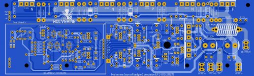
Please help me find any errors. Two photo's and the Sprint .LAY6 files.
Big caps up to 15mm will fit perfect. 5,7.5, 10, 12.5 lead space.
Those big 38mm ones , you might still be able to fit them.
OS
All done , Maybe just some final tweaking.
Please help me find any errors. Two photo's and the Sprint .LAY6 files.
Big caps up to 15mm will fit perfect. 5,7.5, 10, 12.5 lead space.
Those big 38mm ones , you might still be able to fit them.
OS
Attachments
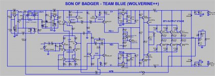
D1 the 1n4148 diode is only rated at a 100V, we have +/-60V rails. We need at the very minimum a 150V part there. The original Badger used a Bav21 I believe.
Here is the spice model.
Here is the spice model.
Attachments
Last edited:
That 1n4148 was just for simulation. Yes , the BAV .... I wanted to see
how the C and reverse leakage would affect this design.
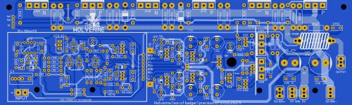
I'm looking for trace errors , device pinout/spacing , reverse diodes ... etc.
Or wrong device names .... just found one. R201/205
OS
how the C and reverse leakage would affect this design.
I'm looking for trace errors , device pinout/spacing , reverse diodes ... etc.
Or wrong device names .... just found one. R201/205
OS
Last edited:
It might be a good idea to add a screw hole or some sort of support on the top left of where the optional input board will be plugging in.
- Home
- Amplifiers
- Solid State
- DIYA store "Wolverine" (Son of Badger) .... suggestions ??