First addon - "the bomb"
My greenamp works , Ive seen these in asia and Indonesia already.
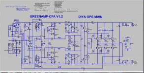
250V/uS slew. oh , boy CFA Goodness. (below)
Perfect with this DIYA board. I DO think the forum will have so much fun with this. I think most current projects here are quite (basic).
Since I am subwoofer based for under 100hz , these CFA "unholy" designs
appeal to me .... they appear to have the same OP FB as the TMC in the badger VFA
... but with current FB - do the HF better than ANY VFA (200V/uS).
They control mid/tweeter with same authority as VFA's can do with
the woofers.
OS
My greenamp works , Ive seen these in asia and Indonesia already.
250V/uS slew. oh , boy CFA Goodness. (below)
Perfect with this DIYA board. I DO think the forum will have so much fun with this. I think most current projects here are quite (basic).
Since I am subwoofer based for under 100hz , these CFA "unholy" designs
appeal to me .... they appear to have the same OP FB as the TMC in the badger VFA
... but with current FB - do the HF better than ANY VFA (200V/uS).
They control mid/tweeter with same authority as VFA's can do with
the woofers.
OS
Attachments
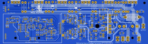
Use solder pad jumpers to make 'removing' the default IPS really easy. Or it is a card bought as part of the kit. A panel of two OPS boards and two IPS boards would be straightforward for manufacturing.
Good idea - similar to the Slewmaster where you can easily change the IPS.
PS hope you can use 1/2W resistors as well.
Last edited:
I've never had a chance to build the Greenamp yet. I'm curious how it compares to Kypton-ND? I'd like to try the class G output stage that was being developed with it.
The layout is looking great so far, but I have another idea that works out great in a few of our amps. If you can rotate the bias pot 90 degrees and give a clear shot to the edge of the board it would allow for bias adjustment without major disassembly of the amplifier (3296X side adjust pot). It doesn't make much difference with the Slewmaster bias circuit, but bias should be set with the amp in assemble form and in normal operating conditions.
Attachments
...it would allow for bias adjustment without major disassembly of the amplifier (3296X side adjust pot).
This would certainly be a good idea for service. The pots I have stocked are "top adjust", so would be a little more work to adjust.
In Aircraft radios/ Amplifiers, many adjustments can be made externally, "on the line". They use holes in the case/ chassis that align with the pots. For bigger repairs, we ship out to "bench shops" for overhaul or repair.
The layout is looking great so far, but I have another idea that works out great in a few of our amps. If you can rotate the bias pot 90 degrees and give a clear shot to the edge of the board it would allow for bias adjustment without major disassembly of the amplifier (3296X side adjust pot). It doesn't make much difference with the Slewmaster bias circuit, but bias should be set with the amp in assemble form and in normal operating conditions.
+1. I wish i had that option for my 5ch honey badger 🙂 I've got it for offset and CCS adjust.
Suppose that you will have access to the bias trimmer, where you will measure this?
It is need to have access to the test point too.
It is need to have access to the test point too.
Bias can easily be measured with the overcurrent connector, either at the protection board if used or with a jumper cable.
It's easier to get access to testpoints then to get a screwdriver in horizontally if it's a tight fit build.
I've done triple ef with this concept, same driver and output bjts, why is the driver pair idle current so low, this way driver transistors are "slower" then output pairs, what's the catch?My greenamp works , Ive seen these in asia and Indonesia already.
250V/uS slew. oh , boy CFA Goodness. (below)
Perfect with this DIYA board. I DO think the forum will have so much fun with this. I think most current projects here are quite (basic).
Since I am subwoofer based for under 100hz , these CFA "unholy" designs
appeal to me .... they appear to have the same OP FB as the TMC in the badger VFA
... but with current FB - do the HF better than ANY VFA (200V/uS).
They control mid/tweeter with same authority as VFA's can do with
the woofers.
OS
I've done triple ef with this concept, same driver and output bjts, why is the driver pair idle current so low, this way driver transistors are "slower" then output pairs, what's the catch?
Excuse my lack of knowledge(sincerely) , but could this be to help with stability / avoid oscillation?
This is what Bob Cordell says causes the shoot through destruction seen with slow output devices.
This is what Bob Cordell says causes the shoot through destruction seen with slow output devices.
Is the idea to keep the OPS devices faster than the drivers to avoid the shoot through? Do you know if the shoot through happened with "real audio" or extreme test condition?
PThanks,
Tim
The shoot through happened in sine wave testing if I recall correctly and was a common problem in many EF3 designs. None of them made it to live listening tests, builders knew there was an issue and moved on to fixing it. Cordell's answer was to increase driver current to give them more current to turn the output devices off, but I'm not aware of anyone actually testing his theory, we all listened to Ostripper's advice and simply selected faster output devices.
Cool, thanks. I have MJL 4302/ 4281 per previous recommended OPS on badger 2.4 , so I'm un affected either way, I was just curious.
I have Bob's book, but I'm not very far along yet. I have some Doug Self books as well.
I have Bob's book, but I'm not very far along yet. I have some Doug Self books as well.
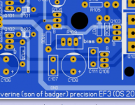
The last mile ....
Swap out driver resistor to your hearts content. The 220R at R111 is the HK680
value. They used this with TO-220 (2SA1837 /2SC4793 ). NJW's go all the way down to 100R.
The board is made to do some tinkerin' (below).
Still have to choose the Servo caps and decide on input plugin/main cap.
Fancy wolverine ... 😀
OS
Attachments

The layout is looking great so far, but I have another idea that works out great in a few of our amps. If you can rotate the bias pot 90 degrees and give a clear shot to the edge of the board it would allow for bias adjustment without major disassembly of the amplifier (3296X side adjust pot). It doesn't make much difference with the Slewmaster bias circuit, but bias should be set with the amp in assemble form and in normal operating conditions.
Got it. I'll do that with CCS pot , as well.
OS
It looks like you have loads of room on the input board! Hopefully Spooky will fit with no issues.
- Home
- Amplifiers
- Solid State
- DIYA store "Wolverine" (Son of Badger) .... suggestions ??