I believe on the original badger you layed it out as a single layer board (bottom layer only). When they ordered the official boards they added the top layer copper to eliminate jumpers, all the holes were plated at the same time making their diameter unintentionally smaller.
I remember doing some research back in the days. So this is what happened ?
Does anybody know what offset the plated through holes entail ?
PS - Sprint ?? Manual with the mind. Got EVERY slewmaster right.
OS
Last edited:
Normally you specify the hole size and the board manufacturer makes the finished size match your spec.
Correct
I think the hole sizes were adequate for a single layer board but needed to be bumped up for tolerancing.
I think the hole sizes were adequate for a single layer board but needed to be bumped up for tolerancing.
Would they adhere to the actual gerber/drill data files ?
OS
Yes, a cheap board house might have looser tolerances though.
From what I saw the hole sizes were actually okay for 1/4Watt resistors. The issue came about when people wanted "higher end" resistors like Dale 1/2W.
I used standard 1/4W resistors, they were a little tight on my board. On one end of the board they slid in fine but the other end was little tight
I copied this from a board house website talking about finished hole tolerances.
"Many manufacturer datasheets expect a PCB manufacturing tolerance of +/-3 mil. Since our process is more precise than this expectation, the fabricated PCB will always meet manufacturer expectations."
"Many manufacturer datasheets expect a PCB manufacturing tolerance of +/-3 mil. Since our process is more precise than this expectation, the fabricated PCB will always meet manufacturer expectations."
I guess we can not teach old the dogs new tricks, so be it ... ltspice & sprint a good pcb design combo 🙂PS - Sprint ?? Manual with the mind. Got EVERY slewmaster right.
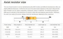
Look at DIN standards 0204, 0207, 0414 use a lead pitch of 10 (tight) or 12.5 (loose) mm, standardize on mm LS, like I use 7.5mm for DO-35
35mil FHS is usually adequate for resistors up to 1/2W, pads can be bigger on the bottom than the top 65T/75B works for me
I am using Vishay MBA0204 and MBB0207 thin films in some designs if you need precision 25ppm parts.
Look at that datasheet as a guide. No barking please 🙂
Last edited:
I guess we can not teach old the dogs new tricks, so be it ... ltspice & sprint a good pcb design combo 🙂
Look at DIN standards 0204, 0207, 0414 use a lead pitch of 10 (tight) or 12.5 (loose) mm, standardize on mm LS, like I use 7.5mm for DO-35
35mil FHS is usually adequate for resistors up to 1/2W, pads can be bigger on the bottom than the top 65T/75B works for me
I am using Vishay MBA0204 and MBB0207 thin films in some designs if you need precision 25ppm parts.
Look at that datasheet as a guide. No barking please 🙂
SMD and micro stuff I DO use more advanced software. Classic amps with
through -hole .... Sprint.
That English builder got that 5ppm with the 3 pair Slewmaster layout.
Auto- routing might not of gotten it right. EF3 layout is an art.
I have seen SO many Japanese OEM EF3's where they add extra components
to counter the parasitics on the PCB.
My HK amp has the type of layout I appreciate. This is why the 680 has
a "fan club".
OS
Not sure if it's helpful or not... I used resisters per the BOM. I might not have the prettiest craftsmanship, but everything fit perfectly tolerance wise.
That was my actual first Sprint creation (Badger). First try , Jason still sells
it.
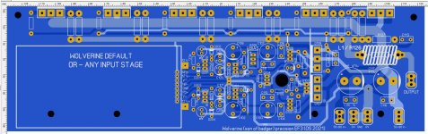
This one is after 20 or more perfect Slewmaster creations.
Also , on this .... Notice the sectional component labeling , Simple BOM
with common values (1,10 ,47uf caps). No special parts.
A few more parts , but more carefully thought out.
A couple 15K resistor from rails to PD+/ND- pins , you could bias and test
the OPS in isolation.
I will make ...
Spooky / Greenamp CFA / Symasui
as addons to this creation.
OS
The tool does not necessarily dictate the quality of the work.
My thinking is, that it would be a great opportunity to,
1) Share and learn a new and popular public domain ecad toolset
2) Use the ecad toolset to develop a new DIYAudio amplifier
Okay, I am done on the ecad discussion. I do not want to derail your thread any longer.
Good luck with your design
My thinking is, that it would be a great opportunity to,
1) Share and learn a new and popular public domain ecad toolset
2) Use the ecad toolset to develop a new DIYAudio amplifier
Okay, I am done on the ecad discussion. I do not want to derail your thread any longer.
Good luck with your design
The tool does not necessarily dictate the quality of the work.
I've done some artwork on Diptrace. Higher learning curve just to have go
manual in the end ... anyways.
Seems to be geared toward RF / digital. The (cool) self-checking is helpful
for a work deadline.
Diptrace does not have 100's of classic amp designs as a reference
(my repairs).
I would use the higher order tools with some of the crazy "bigger" designs
I've seen here in the forum. Or like my PIC powered Nixie clock - perfect !
OS
That was my actual first Sprint creation (Badger). First try , Jason still sells
it.
OS
Just to be clear, I was critical of my craftsmanship in assembly, not yours as a designer. The board is beautiful 🙂.
I am not following into the ecad toolset discussion trap 🙂 sorry
Heiltrim, soldering is usually inspected by viewing the solder side 🙂
Sprint does an excellent job of artwork 🙂
Heiltrim, soldering is usually inspected by viewing the solder side 🙂
Sprint does an excellent job of artwork 🙂
This is what I am going by.
And for semi's by the (multiple sources) PDF's.
OS
Sorry I feel we exhausted this topic but what is Sprint's default through hole diameter for a 1/4W resistor or did you create the parts manually?
Sprint has default macro's. Reflecting an age gone by. And parts no longer
made.
I just looked up -
the Nichicon UV Z/R as the premium BOM EL capacitor.
https://www.mouser.com/datasheet/2/293/e_uvz-1219460.pdf
Made the macro for both the 6.3mm and 10mm version in a minute each.
To Nichicon spec - 47 or 100u/100v for the 10mm's and either 10-22u/6.3mm.
No 80V option for these smaller caps.
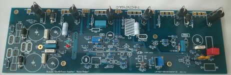
(below) is the result. also , made the diodes and zeners to Vishay specs.
12V regulators are (beefy) all TO-126 ...
Just the main Wolverine to go. IPS/servo , all the services are at the interface.
OS
made.
I just looked up -
the Nichicon UV Z/R as the premium BOM EL capacitor.
https://www.mouser.com/datasheet/2/293/e_uvz-1219460.pdf
Made the macro for both the 6.3mm and 10mm version in a minute each.
To Nichicon spec - 47 or 100u/100v for the 10mm's and either 10-22u/6.3mm.
No 80V option for these smaller caps.
(below) is the result. also , made the diodes and zeners to Vishay specs.
12V regulators are (beefy) all TO-126 ...
Just the main Wolverine to go. IPS/servo , all the services are at the interface.
OS
Attachments
- Home
- Amplifiers
- Solid State
- DIYA store "Wolverine" (Son of Badger) .... suggestions ??