Through-hole components are disappearing, its just a matter of time before all the low signal transistors will only be available in smd. I don't understand the compulsion to continue to design audio circuits with obsolete leaded components. If you want low noise BC550/BC560 transistors then use the smd equivalents BC850/BC860. Same with KSC1845/KSA992, the smd equivalents FJV1845/FJV992 are readily available.
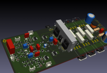
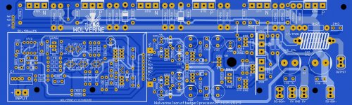
"Wolverine" (Son of Badger) is technically obsolete from a leaded component availability point of view.
Agree 100%
I tried before to get the forum to go SMD before. I'm not scared of it. I even like the idea of those duals in the 6 pin package.
Tubes and phono players are obsolete now. So are freakin' CD players. I have not even seen a CD in 20 years.
This is a gateway project. The modular IPS's can be all SMD.
Point is , if they won't build it - why bother. Just go buy a Chinese class D SMD .... throw it in a box.
Even with SMD , I saw devices and traces so small on my son's new ASUS motherboard that one could not even repair it.
SMD is going the way of disposable prebuilt modular. NO DIY.
OS
I agree (and preaching to the converted), it must be frustrating for you to appease everyone, and it's a catch-22 and as you know there are a number of factors at play:
- The demographics and attitudes of DiyAudio forum members.
- Technological progress and obsolescence ie: CRT TV's and physical mediums (tape, vinyl, CD).
- Consumer product pricing expectations. they don't care what's inside the box.
- The demise of electronic component outlets like Radio Shack.
So we're not surprised (well those of us who work with electronics) when components like high voltage transistors and through hole components disappear and are replaced with different form factors. It's inevitable that at some point Diy'ers will have to accept reality that through hole componentry is living on borrowed time.
It's not all doom and gloom and most of the transistors in through hole are available in smd. I guess what makes it a little easier is we can design two versions of the same amplifier with a little help from our CAD software and other forum members who can contribute to a smd version. It gives everyone an option and it future-proofs the design to some extent.
As an example I took your spooky amp and mashed it together with slewmaster and turned it into a mostly smd design (its still a work in progress).
Attachments
Thanks Indiglo for your suggestions. What surface mount parts are you using for your VAS/Predriver?
For a fully surface mount IPS I'd use these parts. Any other suggestions?
Low VCE (BC550/BC560 Series Equivalent)
-BC849/BC859
-BC850/BC860
-BC846/BC856
High VCE (KSC1845/KSA992 Equivalent)
-FJV1845/FJV992
High VCE VAS/Predriver
-2SC4027/2SA1552 (TTC004B/TTA004B Equivalent)
For a fully surface mount IPS I'd use these parts. Any other suggestions?
Low VCE (BC550/BC560 Series Equivalent)
-BC849/BC859
-BC850/BC860
-BC846/BC856
High VCE (KSC1845/KSA992 Equivalent)
-FJV1845/FJV992
High VCE VAS/Predriver
-2SC4027/2SA1552 (TTC004B/TTA004B Equivalent)
Last edited:
I haven’t double checked the pin out feasibly, but what if some customized to-92 footprints were used. This might allow one to choose either smt or through hole with some slightly bent out legs on the same layout.
Once you go SMT, you can use a large number of dual matched devices from Nexperia, Diodes Inc, and ON (and others maybe).
BC847BS
BCM847BS/DS
BC857BS
BCM857BS/DS
DMMT5551
DMMT5401
and more.
Some part numbers have mismatch below 2%, but 10% is usual. They're cheap.
BC847BS
BCM847BS/DS
BC857BS
BCM857BS/DS
DMMT5551
DMMT5401
and more.
Some part numbers have mismatch below 2%, but 10% is usual. They're cheap.
In regards to the feedback resistor - my preference is to use a one watt resistor or multiple resistors.
Just my $0.02.
Just my $0.02.
I vote strongly for through-hole.
Who cares if through-hole would disappear in 10 years. It might not.
If they would, there would be Grandson of Badger with full SMD.
Let us keep going thru this time.
Who cares if through-hole would disappear in 10 years. It might not.
If they would, there would be Grandson of Badger with full SMD.
Let us keep going thru this time.
With the rate through hole is disappearing I think the timeframe is closer to a year or two. 10 years is dreaming.
Hi OS,
Regarding post 99, furthering my previous question about IPS(s)...
Will the Wolverine IPS be available as a daughter board for people who want to experiment with multiple IPS?
I'd love to do a Spooky (HK990 based) someday, but I'd really like to enjoy your Badger based design as well.
I might try to e-cycle and old chassis and build a separate unit if not.
I'm pretty stoked about this design!
on Electronic Components Distributor - Mouser Electronics Canada
if I look for semi->transistor->active->Through hole BJT, there are 2581 hits.
if like your estimation and they disappear in two years, 2581/(365x2) about 3 per day.
I will go to check next month to see if only 2481 active through hole BJT left active.
if I look for semi->transistor->active->Through hole BJT, there are 2581 hits.
if like your estimation and they disappear in two years, 2581/(365x2) about 3 per day.
I will go to check next month to see if only 2481 active through hole BJT left active.
I thing something is mixed up with Q8 and Q9 connections. R12 should go to the base of Q9, not Q8. R13 should go to the base of Q8, not Q9. Looks like Q9 collector and emitter connections are swapped.
Read the last couple of pages and see what Pete is finding for transistors that are useful in audio applications. Pickings are getting slim fast.
Q8 emitter is connected to the base of Q7, should be collector.
This manual checking is hard on the brain!
This manual checking is hard on the brain!
I vote strongly for through-hole.
Who cares if through-hole would disappear in 10 years. It might not.
If they would, there would be Grandson of Badger with full SMD.
Let us keep going thru this time.
Why thank you , friend.
Full SMD , not sure we are ready for that.
And JW , I found many errors too.
New ones. (below).
Full EBC for Q1/2 /3/4. .lay and pictures. Re-did a lot of it.
PS - the schema is redrawn. Vregs/OPS are unified now. Servo and vregs
still have 2xx numbering.
OS
Attachments

Last edited:
Q8 emitter is connected to the base of Q7, should be collector.
This manual checking is hard on the brain!
Great exercise ... aye.
I took me a few weeks to even GET TO the slew level.
I am now beyond. I'm doing an SMD greenamp IPS now.
Learning the different package sizes. 1206 Resistors/diodes SOT23/89 semi's.
Might do a "dually" SOT23-6 for the diamond pair. Wow , 1206 LED's are
.11c each.
OS
Last edited:
- Home
- Amplifiers
- Solid State
- DIYA store "Wolverine" (Son of Badger) .... suggestions ??