The breeze came along
And broke my tap.
Went to cry to my wife. She said, can't you heat it to get it loose? The smart lady. Yes I said, great idea, torch it, the alu expands, the iron not, then wring it loose.
What should I do? Yust start over? I tried to keep it all nicely lined out. .
Appears to be enough meat on the broken tap that you can try using flat end pliers and wiggle it out. Heating it with a blow torch would damage the black anodize finish?
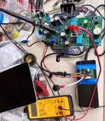
049 lives!
I had help today, so after a last check to see if everything was still working and sounding OK while it was still in pieces on the workbench, we put the case together.
So far I had only heard the amp on old workshop speakers using an old Squeezebox Classic source. Half an hour ago we moved it to my bedroom, and my helper hooked it up to my bedroom speakers (Avalon Studio Monitors) and source (Transporter). No preamp at the moment, and even with reasonably low efficiency Avalon's and only 2V RMS single ended max output of the Transporter, plenty loud enough for the bedroom. First impressions are good, but best listening position is in bed, so I should know more tonight!
Thanks Nelson and everyone at diyaudio for making this possible!
Nice to see that another one has come together. 
You will like it even more after it has been playing for a couple days.
You will like it even more after it has been playing for a couple days.
First impressions are very quiet, relaxed and warm while at the same time crystal clear. No mean feat!
I listened to some solo piano (Haydn piano sonata's, Alfred Brendel) first and solo acoustic guitar (Pat Metheny, One quiet night). Low volumes only so far, but with little background noise (midnight haha) and such a beautiful relaxed sound I have not felt the need to turn it up. Yet 🙂
I listened to some solo piano (Haydn piano sonata's, Alfred Brendel) first and solo acoustic guitar (Pat Metheny, One quiet night). Low volumes only so far, but with little background noise (midnight haha) and such a beautiful relaxed sound I have not felt the need to turn it up. Yet 🙂
Last edited:
Dreadnought Board #1
It is quite a busy board, as you all can see. Lots of parts that need to be installed in the correct positions. I really appreciated the Customer Part# attached to the line items in the Mouser BOM. It definitely helped with the installation. I took my time with the assembly over a couple days.
The board powered up with no issues. Setting the switching frequency was very straightforward. Final POS_BOOSTED voltage is just under 58V. Having the SMPS and its little filter board separate from the amp chassis was convenient.
Attachments
Yeah, I had to buy a new lab power supply for VFET front end board development and debug; Front Ends run from (+36V, GND) but my workhorse supply only went up to ±30V and 2A. Since the FE boards were designed and built before the final SMPS choice was made, I bit the bullet and bought a single polarity supply from Circuit Specialists: (this one). It has plenty of grunt, enough to power a Front End card AND a class A VFET Amp Channel Card.
It's what powered the early prototypes of all six Front End cards, and also the early prototypes of the Ship Of Theseus PNP amp channel card. So naturally I bought another one of these power supplies, because owning two is better than owning one.
It's what powered the early prototypes of all six Front End cards, and also the early prototypes of the Ship Of Theseus PNP amp channel card. So naturally I bought another one of these power supplies, because owning two is better than owning one.
I don't think I've seen anything as formal as a mission statement for the new VFET front end boards, but they all offer some alternatives to the one that comes with the standard kit.
Bulwark and Scourge drive their Edcor transformers with different types of discrete amplifier/buffer circuits. Bulwark has the option to add some extra gain above what is provided by the transformer. Scourge is a straight buffer, very reminiscent of the Mountain View front end for the M2x. Both of these front ends have a passive RC filter network on the incoming 36V power. On their own, these filter networks have the potential to improve stereo separation and imaging. By omitting the initial 27R (or 33R) resistor, 470 uF will be present to filter the 36V power for the whole amp. Something that I found worthwhile, even more so if it is increased to 1000 uF.
The Dreadnought and Marauder front ends eliminate the Edcor transformer and use on-board power boosters to allow sufficient output voltage swing. The booted power can be thought of as dual-mono PSU for the front ends. Probably the place where it will have the most impact. The amplifier circuits themselves are quite different from the others. Dreadnought is a very high output impedance transconductance amplifier, which should have a different sound. Marauder uses a bunch of high voltage opamps, for those who like to play with such things. Kind of the opposite of Dreadnought, as it will have a very low output impedance. Both of these amplifiers have adjustable gain, so one can taylor the overall gain of the VFET amp to suit the system.
That is just my take. I'm sure others will find their own reasons for trying the different front ends. I don't know enough about FE#5 or FE#6 to speculate on those. I am working on some vacuum tube front ends, just because tubes are fun.
I will be building the Dreadnought once the parts arrive. I thought it would be a really nice contrast to the stock FE. I do like the stock amplifier very much. Dreadnought implements some "tricks" to maximize performance that I'm currently reading about in Bob Cordell's book. I like the boosted rail, the improved filtering, the IPS degeneration and current mirror load, polarity invert option, etc. And I plan to do the signal coupling with film caps both in and out. It should be interesting.
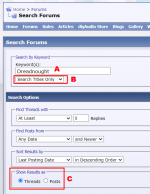
Just about everything that is written about Dreadnought, can be found using the simple trick disclosed in Figure 1 below.
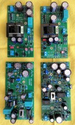
A quick peek at the schematics reveals that Marauder contains two opamp chips. One is a standard voltage (max 36V supply) OPA2134 dual, and the other is a higher voltage (max 60V supply) OPA552 single. Carefully note that TI has decompensated the '552 and it is not unity gain stable -- intentionally.
Both Marauder and Dreadnought include a slide switch on the PCB, with a pair of LEDs that indicate which position is currently selected. Neither Bulwark nor Scourge has a slide switch. In the Figure 2 photo below, you can see that this Marauder board uses a teal colored KEMET 2.2 microfarad polypropylene film capacitor at its input. This Dreadnought board uses a black colored Panasonic 2.2 microfarad polypropylene film capacitor at its input. Both of their Mouser P/Ns are tabulated in the Detailed Parts List.
Head on over to the Forum thread about the optional Front End cards, if you want to read more or start a discussion.
_
Attachments
Last edited:
Hello all, #37 is done and wait for it and *******************POP goes the cap!!! Well i though i did a thorough check but the BIG CAP just got over looked. I don't have the prototype board i just put it in backwards. OK so this is my second diy amp, and everything has been supplied for me. My question is can i get the Cap from the diyaudiostore or do i need to order from digikey ect. and is there a upgrade sense i gonna put my first order in any way? (also i have been getting ready for a F5 / F5+ build slowly getting parts maybe i can get some advice)
Erin
Erin
Ahh, too bad about blowing the big cap. The Rubycon caps that came with the kit are decent ones. If you are looking for an alternate, these would be a good way to go:
https://www.mouser.com/ProductDetail/Nichicon/LKG1H103MESCBK?qs=4lWw5qRttGJcrVu0WisRew==
https://www.mouser.com/ProductDetail/Nichicon/LKG1H103MESCBK?qs=4lWw5qRttGJcrVu0WisRew==
Or this...
https://www.mouser.dk/ProductDetail/Nichicon/LKS1H103MESB?qs=ppWA7IX8Fw4y5eWYHHXypQ==
This one is in stock.
https://www.mouser.dk/ProductDetail/Nichicon/LKS1H103MESB?qs=ppWA7IX8Fw4y5eWYHHXypQ==
This one is in stock.
I haven't got access to my VFET amp for a few days but while away I am thinking about installing a couple of things...
Would someone be kind enough to just tell me the size of the ventilation slots we have in our top & bottom pannels? Seen from the top, I just need the width / the small dimension of a slot, not it length...
Many many thanks
Claude
Would someone be kind enough to just tell me the size of the ventilation slots we have in our top & bottom pannels? Seen from the top, I just need the width / the small dimension of a slot, not it length...
Many many thanks
Claude
I measured the slots in my chassis at 4.8 mm in width. Just for completeness the length was 29.2 mm.
The second Dreadnought board powered up the same as my first one. Boringly predictable, predictably boring. That’s a good thing for engineers. 😉
So, just to add something interesting, I hooked the input power up to one of my 28V SMPS units. Without any adjustments, the onboard Boosted-power achieved 42.7 Volts. Possibly still good for about 40V peak-to-peak signal out?
So, just to add something interesting, I hooked the input power up to one of my 28V SMPS units. Without any adjustments, the onboard Boosted-power achieved 42.7 Volts. Possibly still good for about 40V peak-to-peak signal out?
Apply an input sinewave (I recommend 30 kHz) and dial up the amplitude until juuuuuust barely visible clipping on the output. Overlay delta-Y scope cursors, job done.
But your VFET amp channel cards have their bias potentiometer lovingly adjusted and fine-tuned for 36V DC input. Dropping the supply down to 28V means you'll get less output power, AND you'll operate the magic flux capacitor (VFET follower) at a bias point away from the optimum "sweet spot" as determined by Gandalf Wizardo Merlin, who supplied your magic flux capacitor in the first place.
But your VFET amp channel cards have their bias potentiometer lovingly adjusted and fine-tuned for 36V DC input. Dropping the supply down to 28V means you'll get less output power, AND you'll operate the magic flux capacitor (VFET follower) at a bias point away from the optimum "sweet spot" as determined by Gandalf Wizardo Merlin, who supplied your magic flux capacitor in the first place.
I was really just curious about what would happen with the boosted power voltage. My VFET amp will continue to run on 36VDC at the power inlet. Don’t want to mess with Mr Fusion power and special flux capacitor.
Still learning about how this switching PSU works.
Still learning about how this switching PSU works.
- Home
- Amplifiers
- Pass Labs
- DIY Sony VFET Builders thread