If you're thinking about installing one of the other, optional Front End cards, you might be interested to know that I changed (simplified) the circuit designs and the PCB Gerbers yesterday. Full details in post #141 HERE.
The first release of these Front Ends jumped thru hoops to ensure compatibility with a bunch of different power supply arrangements. But we have discovered that those different PS options are not actually needed and won't be used. So I've simplified the Front Ends by removing the unnecessary parts. There are now fewer components to buy, fewer parts to stuff and solder, and fewer opportunities for build errors.
The first release of these Front Ends jumped thru hoops to ensure compatibility with a bunch of different power supply arrangements. But we have discovered that those different PS options are not actually needed and won't be used. So I've simplified the Front Ends by removing the unnecessary parts. There are now fewer components to buy, fewer parts to stuff and solder, and fewer opportunities for build errors.
@Tungsten
I think you did a great job with your new VFET power supply.
I also appreciate all the work you have done with the ACA.
Everyone has their reasons for considering modifying any project and their ideas about how to do it.
My comment was directed more at the feasibility of using the F1 PS circuit and if or why it might not be suitable or desirable to use for these amps.
Because I don’t have the ability or experience to design or build more complex circuits myself I search for what appears to be the simplest solutions.
@Ben
So if the F2 amp circuit itself is responsible for quiet power cycling, then I wonder how the F1 PS would perform with the VFET or ACA during their cycles.
Would the thump still be present when the VFET powered down? Would the ACAs still “fart” on start up?
I have a pair of the Dreadnought boards in hand, thanks to a generous forum member. I will be building them up over the weekend, once my Mouser order arrives. I'm looking forward to hearing how the amp sounds with a different front end.
An interesting, if perhaps unintended, bonus of the new front end designs is that they will add extra capacitance to the power supply rails inside the amp, by virtue of removing the diode bridges. So intrepid amp builders will get to hear not only the new circuit, but also some improved stereo separation and imaging. Not unlike what I did way back when, before going all the way with a new linear PSU.
😉
Progress...
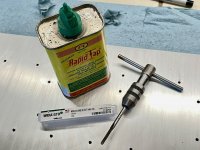
Despite mixed recommendations, I had no trouble running a bottoming tap through all of the M3 heatsink mounting holes. Took me about 30 minutes to do them all, plus ~15 minutes prep & cleanup.
I had already decided I wanted to clean out the lime scale deposits anyway, and getting an extra thread or two at the bottom of each hole seemed like an easy bonus. Since it only took 10 minutes to do just the holes I planned to use, I figured what the heck - I'll spend the extra 20 minutes and do the rest.
Aluminum can be a bit fussy, so here are a few tips for those who don't tap aluminum all that often:
• Use a good quality hand tap, not a cheap department store tap, or one designed for machine tapping (unless you're actually going to use a machine, in which case... you probably don't need my advice!). The one I used is made by Widia / Greenfield Tap & Die, McMaster 8305A52 - $8.50.
• Use a tap with straight flutes for bottoming / blind holes - spiral point taps will push chips downwards and pack them into the bottom of the hole. Spiral flute taps tend to be fragile in small sizes, and unnecessary.
• Avoid coated taps - aluminum tends to stick to most tool coatings (like TiN), and the coatings really don't do anything useful when hand tapping. Plain HSS works great.
• Use an appropriate cutting or tapping fluid. 2-in-1 oil, motor oil, or other generic household lubricating oil will work fine in a pinch.
• Once the taps start to cut, run it in 1/4 to 1/2 turn, then back it out a partial turn, and then continue. Repeat, backing out a bit every ~1/2 turn or so. This will break up the aluminum chip and help prevent clogging.
• Twist the tap in using the inner portion of the T-handle tap wrench, to avoid applying excessive force and have a better feel for how the tap is cutting. If you turn the tap using the outer ends of the T-wrench, you can easily break the tap off in the hole, and then you're in a real pickle. Easy does it. You'll know when the tap has reached the bottom of the hole.
• Brush the aluminum chips off of the tap between each hole to help the tap cut cleanly every time.
For final clean-up, I used a can of Brakleen brake cleaner spray (Best done outdoors - eye protection & nitrile gloves strongly recommended!) ... just one very short burst in each hole putting the little applicator tube right in the hole will blast out any remaining cutting fluid & chips, leaving a squeaky-clean part.
Happy tapping y'all!!
Attachments
Last edited:
.............................
@Ben
So if the F2 amp circuit itself is responsible for quiet power cycling, then I wonder how the F1 PS would perform with the VFET or ACA during their cycles.
Would the thump still be present when the VFET powered down? Would the ACAs still “fart” on start up?
I don't have an ACA or Sony VFET Part 1 so I don't have any direct experience regarding turn-on noise or thump for them.
However, I do have a pair of single ended choke loaded 2SK180 mono-blocks and a pair of single ended CCS loaded THF-51S mono-blocks that have First Watt type of power supplies. They do differ though in that they are CLC instead of CRC, with Hammond 159ZJ chokes, and they also have 88,000 uF total per channel.
My amplifiers are similar to the ACA and Sony VFET Part 1 in that they are single ended and have output coupling capacitors. Also, the THF-51S amp is CCS loaded, as are the ACA and Sony VFET Part 1.
Both of my amps do not have noise at turn-on or turn-off.
I would like to add that the no turn-on and no turn-off noise is with 103dB speakers. Furthermore, there is no hum or hiss either.
Last edited:
 hifiZen thanks good instrutions
 Ive just recently learnt the easy fix if you break your tap in the hole
turn the heat sink upside down and start again, took me a few hrs of sweat and tears to work that out.
Some progress today...
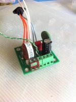
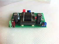
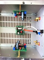
I decided to build the VFET in a modular way, so that I can add SMPS filters after the existing std one, swap easily and quickly FE boards, possibly switch between direct VFET OS and FE + OS stages, dismantle and mount things quickly without to have to mess with lot of work, play with additional PS caps etc.
At the end I decided to use tall stand-offs (better for cables, less heat, allows additional bypass caps underneath) and screw connectors. I don't like the latter, especialy in the signal path, but I have to grow and accept they are indeed doing a good job. The connectors aren't cute, but they are practical. As this amp is for my wife, I asked her what she thought about the ugly connector bricks etc. - She said the VFET amp casing was cute looking, and as for its inside, she said "seriously, do you expect anyone else but you too ever look inside not even mentioning opening it, LOL" - she got a point. I have to live with it, at least while I experiment.
They are green connectors for everything related to power supply, and blue connectors for signal only. On top, I marked red all poles that are "+", to avoid any confusion with the others (mainly grounds). It looks big and ugly on pix, but once you have just the top lid open and all build up inside, space and light are not great so you better make things very obvious to hopefully avoid any mistake.
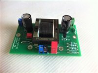
Last but not least, the astute reader will have noticed that on the filter two 2 pole connectors would have done the job to allow an easy additional SMPS filter connection, but while at it I found to have an entire row of connector more practical - but it isn't necessary: 2 V+ and 2 Grounds awould have been enough.
As things are, I can do many things just opening the top pannel and nearly everything taking off both top and bottom pannel, which is done easily. It is quite different obviously from the recommended assembling and all that hassle is only worth considering if you want to test various things - otherwise just follow the regular excellent build, job done once for all.
I need to finish the cabling and think about the 2 additional 4PDT switches... whenever I find the time.
I am now considering altering slightly the OS connections, in hope to reorganise the Grounds differently. TBH, they are of course all connected together so I doubt it makes a real difference, but I like to think about a sequence where the ground next to V+ is PS related, then G spare, then LS G (bigger signal), then small signal / FE G...
To be followed...
Claude
I decided to build the VFET in a modular way, so that I can add SMPS filters after the existing std one, swap easily and quickly FE boards, possibly switch between direct VFET OS and FE + OS stages, dismantle and mount things quickly without to have to mess with lot of work, play with additional PS caps etc.
At the end I decided to use tall stand-offs (better for cables, less heat, allows additional bypass caps underneath) and screw connectors. I don't like the latter, especialy in the signal path, but I have to grow and accept they are indeed doing a good job. The connectors aren't cute, but they are practical. As this amp is for my wife, I asked her what she thought about the ugly connector bricks etc. - She said the VFET amp casing was cute looking, and as for its inside, she said "seriously, do you expect anyone else but you too ever look inside not even mentioning opening it, LOL" - she got a point. I have to live with it, at least while I experiment.
They are green connectors for everything related to power supply, and blue connectors for signal only. On top, I marked red all poles that are "+", to avoid any confusion with the others (mainly grounds). It looks big and ugly on pix, but once you have just the top lid open and all build up inside, space and light are not great so you better make things very obvious to hopefully avoid any mistake.
Last but not least, the astute reader will have noticed that on the filter two 2 pole connectors would have done the job to allow an easy additional SMPS filter connection, but while at it I found to have an entire row of connector more practical - but it isn't necessary: 2 V+ and 2 Grounds awould have been enough.
As things are, I can do many things just opening the top pannel and nearly everything taking off both top and bottom pannel, which is done easily. It is quite different obviously from the recommended assembling and all that hassle is only worth considering if you want to test various things - otherwise just follow the regular excellent build, job done once for all.
I need to finish the cabling and think about the 2 additional 4PDT switches... whenever I find the time.
I am now considering altering slightly the OS connections, in hope to reorganise the Grounds differently. TBH, they are of course all connected together so I doubt it makes a real difference, but I like to think about a sequence where the ground next to V+ is PS related, then G spare, then LS G (bigger signal), then small signal / FE G...
To be followed...
Claude
Attachments
@hifiZen: Tapping aluminum is a breeze compared to tap threading steel. I've found a centre punch and a drill press to be valuable tools for accuracy in hole position.
@ Ben Mah: I'm looking forward for something grand with the earlier Tokin purchase few months ago. I've found the 8 or 10 watts in the VFet lottery release to be a bit lacking with my 104db efficient speakers. At times I DO love my rock music LOUD in excess of dance club SPLs. I'm still quite baffled with the common source PP Sony VFet v1 as that surely vibrates the door handles in my house; it's transient response is right there. The power of the bass is something that the VFet lottery amp lacked (and perhaps likely so with less available watts going down to 4 ohms or less). Also i'm not all convinced on the performance of the supplied SMPS. Yes it may measure quiet, but I think the low freq response could be improved with a linear power supply and lots of uF. Or it could just be the difference between SE vs PP designs.
@ ClaudeG: great work!!
@hifiZen: Tapping aluminum is a breeze compared to tap threading steel. I've found a centre punch and a drill press to be valuable tools for accuracy in hole position.
@ ClaudeG: great work!!
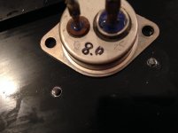
The breeze came along
And broke my tap.
Went to cry to my wife. She said, can't you heat it to get it loose? The smart lady. Yes I said, great idea, torch it, the alu expands, the iron not, then wring it loose
 .
. What should I do? Yust start over? I tried to keep it all nicely lined out. .
Attachments
Use the good one... pivot the critter a bit and try again—but way slower! I have also had taps break just due to careful use over time... fatigue.
It happens.. One of my old Hafler chassis ACA still has a broken tap stuck in one of the heatsinks. Only thing to do is drill another hole. Use a diamond sharpening stone to grind down the top of the broken tap. It will be impossible to remove because there is nothing to grab with pliers.

I took a chisel and just gave a big wham, the protuding part is now in a corner. What went wrong? I drilled 3mm and forgot to then drill 3.2mm. 🙄
Apologies for bothering you with this off-topic part.
Apologies for bothering you with this off-topic part.
yes, heat it some
even heat-gun can help, sometimes Torch temperature is not needed
Only a torch would work, the heatsink is .33/watt (Reichelt SK108)
I once had an Alfa 1300 and a headscrew broke off. A friend worked in a Maserati shop. He welded on a bolt, the alu expanded, the bolt could be taken out . . . I know it works.
You know, smart wifes . .
Long long ago in a studio, the recording engineers wanted to dub a session track, ran into a problem; I had no idea, my girl-friend said, why not insert a piece of paper, the bias will be less active. By far outsmarted me.
Which kinds of taps do you use?
If "hand taps" they come in a set of three and the first one takes very little, next one a little more and the last one makes the final thread. I use those and have never broken a tap 🙂 ....I also do a little forward the backwards.....and so on....then the thread can be made using less torque. The taps I have are either HSS-G or HSS-E steel quality. HSS is not just "HSS".
If "hand taps" they come in a set of three and the first one takes very little, next one a little more and the last one makes the final thread. I use those and have never broken a tap 🙂 ....I also do a little forward the backwards.....and so on....then the thread can be made using less torque. The taps I have are either HSS-G or HSS-E steel quality. HSS is not just "HSS".
With regard to turn on / turn off thumps, the next vfet version has a relay as part of the power supply filter that shorts the output to ground, this being needed because the n channel circuit has a thump where the p ch version did not.
This same filter board can be fitted to other single ended amplifiers.
This same filter board can be fitted to other single ended amplifiers.
Which kinds of taps do you use?
If "hand taps" they come in a set of three and the first one takes very little, next one a little more and the last one makes the final thread. I use those and have never broken a tap 🙂 ....I also do a little forward the backwards.....and so on....then the thread can be made using less torque. The taps I have are either HSS-G or HSS-E steel quality. HSS is not just "HSS".
I have the set of three - now two. 🙄 And I have a set of 'all-in-one stroke' but the depth is less. The problem was my negligence.
- Home
- Amplifiers
- Pass Labs
- DIY Sony VFET Builders thread