A couple of us did try adding extra capacitance to each channel after the PS filter. It was beneficial.
power supply connection in the diagram p3
The one thing (for now) that has me confused is the power supply filtering diagram on page 3, the positive connection of the switching supply goes to ground and the negative supply goes to the power switch. Should this not be the other way around, or should the caps and the LED polarity be inversed?
The one thing (for now) that has me confused is the power supply filtering diagram on page 3, the positive connection of the switching supply goes to ground and the negative supply goes to the power switch. Should this not be the other way around, or should the caps and the LED polarity be inversed?
That was a typo. Mark Johnson wrote about it in the other thread.
Plus from SMPS goes to capacitor plus, and SMPS minus goes to ground.
Regards, Claas
Plus from SMPS goes to capacitor plus, and SMPS minus goes to ground.
Regards, Claas
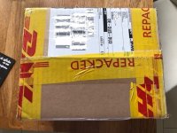
The parts kit arrived already this morning.
Apparently DHL Express wasn't sure if the contents were dangerous, because they had opened the package ... looks like the transformers in the front end package aroused some suspicion 😀
Of course, we already know that this amp is "da bomb", to quote Zen Mod ... 😛
Regards, Claas
Apparently DHL Express wasn't sure if the contents were dangerous, because they had opened the package ... looks like the transformers in the front end package aroused some suspicion 😀
Of course, we already know that this amp is "da bomb", to quote Zen Mod ... 😛
Regards, Claas
Attachments
Got both parcels as well. Thanks a lot to everyone involved!
For some reason DHL from the US was one day quicker then FedEx from Italy 😀
For some reason DHL from the US was one day quicker then FedEx from Italy 😀
You do, huh?
I’ll take that bet…
Try them. You’re going to be amazed.

Let the challenge begin. If the Vfet sounds great with my NS1000 I will be the happiest guy on my block! With the prices that a B2 is going for these days, I really hope the Sony Vfet can drive them.
I looked at the Votex 10 (the 15's look sold out) and that looks really good and a deal at that.
Looking forward to building the amp and firing it up.
As mentioned previously, the VFET amp punches above its weight class. A number of us have been pleasantly surprised by the dynamics, even with moderately efficient speakers. My 1988 vintage Vandersteens do quite well.
The trick is a little extra capacitance on the supply rails, which the new PS filter board takes care of.
The trick is a little extra capacitance on the supply rails, which the new PS filter board takes care of.
Let the challenge begin. If the Vfet sounds great with my NS1000 I will be the happiest guy on my block! With the prices that a B2 is going for these days, I really hope the Sony Vfet can drive them.
I looked at the Votex 10 (the 15's look sold out) and that looks really good and a deal at that.
Looking forward to building the amp and firing it up.
keep- checking on the 15's. He has more but may be waiting for more parts ( circuit boards or comp. drivers).
So, would it merit for us P channel owners to “replace” the current filter with the one designed for the N channel? Would it be beneficial to put it in addition to it? Build something “in between” and, for example, avoid the relay on the O+ for the speakers?
Curious to know what you guys think? Perhaps the store is going to make the new filter available as a kit or PCB?
Thanks,
Rafa.
Curious to know what you guys think? Perhaps the store is going to make the new filter available as a kit or PCB?
Thanks,
Rafa.
Well, since the new VFET pt 2 filter board is not available separately, I recommend simply adding the extra capacitance onto the VFET pt 1 OS boards. The caps can be 1000 uF or 1500 uF, 50V. Connect them between V+ and G.
Try it. That will get you the main benefit of the new filter board, and more easily.
Try it. That will get you the main benefit of the new filter board, and more easily.
Just did the mod to mine.Had an empty hole for one and bent lead over right angle for the other,almost looks factory and took only a few minutes.Now to see if I can hear a difference.If not it helps the filtering and costs almost nothing.

Great idea to draw the 2-pole switch the way you did, it will comfort people who had difficulty interpreting the previous drawing.

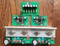
Looking good!
Nice Oak hardwood floor too 😉
A set of good pictures like this can help make a crowd-sourced DIY assembly guide.
Nice Oak hardwood floor too 😉
A set of good pictures like this can help make a crowd-sourced DIY assembly guide.
Great idea to draw the 2-pole switch the way you did, it will comfort people who had difficulty interpreting the previous drawing.
And now I see clearly that the relay [I asked myself earlier in this thread, why not a DC relay 😕 ??] is not for DC but just for a low current AC.

- Home
- Amplifiers
- Pass Labs
- DIY Sony VFET Builders thread