I can confirm: those binding posts are awesome! Installed them on my VFET / Ship Of Theseus amp and absolutely love the way they work. Five stars, would buy again.

Hi guys
Yes, sorry, the speaker posts and I meant the parts reference / numbers, as I thought they came God knows from what manufacturer!
They are awsome and although I go on a weekly basis in the DIYA shop... I never noticed them!!!
Many thanks to all and special mention to Jason who was able to decipher me LOL
Enjoy music
Claude
Yes
Ok so were are you at on this. Lets get this going. Are we talking 2U amp case to match with fins and inverted V front plate and a red / blue Led power button.
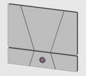
Did up a quick 3D sketch for a potential PSU chassis front panel concept, shown here stacked beneath the amp front panel for the visual. The panel could be installed either right side up to match the V angles on the amp, or inverted depending on preference. The first three are with a slightly smaller EAO power button, the 4th is with my original choice of AV25 (alas TE's step file doesn't show the illuminated ring).
These ones show a 65mm high front panel, chosen for aesthetics, but will likely need a slightly different height in order to work with an economical side extrusion - TBD. Another thought that crossed my mind is that although I intend to use it with SMPS modules only, some others might like to order a chassis which can fit an appropriate toroidal + linear supply caps, so it might be good to leave enough interior Z height for that.
And of course, I still need to cost this out and see if it's palatable or not...
Ok so were are you at on this. Lets get this going. Are we talking 2U amp case to match with fins and inverted V front plate and a red / blue Led power button.
Attachments
Last edited:
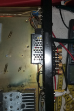
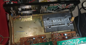
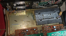
Getting Sony TA 4650 Chassis ready for whatever Single Ended VFET wonderment comes from NP-verse for various VFET devices.
Small SMPS powers the old built in preamp great (complete with tone controls and volume knob) and a couple of inputs. Old preamp sounds great with this little power supply through headphones. On Off switch works great, but have to figure out how to light up green LED in button. Upgraded the binding posts. Now, just needs cards and I need to test my various VFETs (unless I win lottery). Can also attach speaker outputs to headphone output circuit for headphones.
Plenty of room for cards and additional 36v SMPS box.
Attachments
Last edited:
Though you seem to have the version with the slightly taller heat sink, I would not think that it's up to the job of anything over 3 to 5 watts stereo as it stands. (I assume you're using the heat chimneys). Might be worth testing it.
I'll test it when the time comes. I think it will work because each heat sink was intended to work with relatively high bias 100 watts Class AB. That should be OK with 20 watts class A. When I get to that point, I will hit it with a heat measuring gun to see how hot it gets and change strategies as appropriate. I have four of these heat sinks. As you can see from the holes, each heat sink is designed to carry six of the j18/k60 types in class AB operation.
Nobody seems to like the heat sinks for the job, but there's plenty of time to check them out and test them going along. I could flank two if necessary, plenty of room to do that.
Nobody seems to like the heat sinks for the job, but there's plenty of time to check them out and test them going along. I could flank two if necessary, plenty of room to do that.
Last edited:
Sony TA-4650 Stereo Integrated Amplifier Manual | HiFi Engine
Sony TA-5650 on thevintageknob.org
I think that it's about 30W. Testing will tell all you need to know. You could possibly just mount a large resistor on it for testing and wind up the juice. The TA 5650 was about 70W.
Sony TA-5650 on thevintageknob.org
I think that it's about 30W. Testing will tell all you need to know. You could possibly just mount a large resistor on it for testing and wind up the juice. The TA 5650 was about 70W.
Last edited:
LOL! The heat sink is the same for the 4650, 5650 and one channel of the 8550. The 8550 puts out 100w per channel, but measures at 125w. So, it's over-rated for the 4650. It's a good chunk of heavy aluminum. The one in there is actually from an 8650, rated at 80W per heat sink. It will be tested in due course.
Oddly enough, somebody in the day measured the 4650 and found that it put out 60 watts RMS at one percent THD, so it was also conservatively rated. I think the 5650 also was measured almost to 80w/ch RMS.
Oddly enough, somebody in the day measured the 4650 and found that it put out 60 watts RMS at one percent THD, so it was also conservatively rated. I think the 5650 also was measured almost to 80w/ch RMS.
Last edited:
I know, I have each of those models, a few others too.
(Actually I've a TA 8650 not the 8550)
(Actually I've a TA 8650 not the 8550)

Perhaps a bit OT, but I hooked up my SMPS Sony TA 4650 preamp section for a test on larger system. Full range signal>SMPS TA4650 preamp>First Watt M2 (fully warmed up)>full range planar speaker. The preamp was dead silent and sounded great with the M2. Tone controls not only work but are useful. This is surprising for something well past 40 years old. Sound was high, wide, deep, detailed and not even vaguely harsh. As an old tube head, I would say it sounded like tubes with discipline. It seems a perfect companion piece for the M2 in that context. I am very familiar with these preamp sections, and it sounds better than ever with the SMPS for whatever reason.
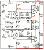
This makes me curious about the phono section (which is not active) because it contains a small signal VFET gain stage with a couple of beefy looking small signal VFETs. It is one of the very few VFET small signal gain stages ever put in a component.
I was wondering if somehow it could be converted to a pure flat gain stage by bypassing the RIAA circuitry. That would be nice complementary input for the Single Ended VFET amp if it were a flat amp as another alternative to the Edcor input. This section could also be powered by a small, separate SMPS (48v low current with a dc power doubler). Diagram of the phono section shows both channels.
Attachments
Last edited:
It's small signal RIAA amp. I was wondering if removed the RIAA filter by snipping the cap resistor feedback loop if it would work as flat amp, or would need other circuit modifications, or would just blow up i.e. c104 c105 R107 R108 feedback removed with a snip. It looks like a 'passive' RC correction circuit. Also don't know what that would do to gain. Just spitballing over the small signal VFET.
I understand what you mean by needing more swing to drive next section.
I understand what you mean by needing more swing to drive next section.
Last edited:
- Home
- Amplifiers
- Pass Labs
- DIY Sony VFET Builders thread