I can maybe order a standard FE board later and then just don't install Edcor and only install the "JFET parts". Then install jumper wires instead of Edcor.
-D output.....does the - (minus) indicate the phase of the signal?
-0 indicates that the output is negative phase?
-D output.....does the - (minus) indicate the phase of the signal?
-0 indicates that the output is negative phase?
Unfortunately it doesn't work that way. On this particular circuit you need a phase inverted source in addition to a phase inverted output to get correct absolute phase and negative phase second harmonic.
The upcoming N channel does not need inversion at all.
I was somewhat afraid of something like this, but alas the lottery system didn't give you the possibility to chose.. but hey, not complaining here.
But in an active system I think the N type would be more easy to implement...
It is not quite that simple. The Edcor transformer is used for galvanic isolation as well as gain. The D– output is what we would normally think of as signal ground, except that it is wired to the 'input' terminal of the Output Stage. The D+ output is wired to the G terminal of the Output Stage. The –O output is wired to the negative (black) speaker terminal.I can maybe order a standard FE board later and then just don't install Edcor and only install the "JFET parts". Then install jumper wires instead of Edcor.
-D output.....does the - (minus) indicate the phase of the signal?
-0 indicates that the output is negative phase?
Mark Johnson's FE boards include designs with and without the Edcor. Those without use coupling capacitors on both outputs. (A different style of galvanic isolation)
I see.....I must study the schematic more closely.....I only observed that there was a coupling cap from JFETs to Edcor and also at the input to the output stage.....so I just thought....that is fine.
First I build everything as in kit.....even the red LED I think I will use 🙂
....or maybe some kits have blue LEDs.....even 6L6 use a blue LED.
First I build everything as in kit.....even the red LED I think I will use 🙂
....or maybe some kits have blue LEDs.....even 6L6 use a blue LED.
But in an active system I think the N type would be more easy to implement...
P type is connected in opposite polaritys directions see on article schematics
but from chassis outside inputs and outputs absolute phase is respected.
Red is + and Black is -
N type Vfet just don't reverse (-)(+)polaritys inside the chassis
but again from the chassis outside is the same thing like with P channels Vfets.
Red is + and Black is -
Still need to take care about absolute phase on 3 channels.. unless I am mistaken, which is quite probable ...
I must say that P- VFET amp polarity bit is quite interesting from an intellectual POV...
Say you have a conventional non-inverting source, say you run direct to the VFET board without any FE. Now, at LS output, you get 2 possible results regarding "absolute polarity and H2 phase"... what are these then?
I mentioned 2 possible results because you can connect your speakers to the terminals as recommended in the paper or inversed.
I understand now you won't get "absolute polarity AND negative H2" as a possible solution, but what do you get then? Is one of the two results perhaps giving you "inverse absolute polarity AND negative H2"?
If so, would that be when connecting the speakers the resverse way from what is in the paper (eg running the LS as in common amps)?
Headache LOL
Claude
Last edited:
Power supply conundrum...
Hmm, so on a purely aesthetic basis, I want to have either an internal or secondary-chassis-enclosed power supply. There's nothing wrong with the Meanwell brick from an electrical standpoint, and I have no compunction about using an SMPS to power this amp... the magnetic field isolation benefit of physical distance is actually a nice benefit. I just personally don't like power bricks cluttering up the floor behind the stereo rack. And I feel a nice amp like this is deserving of something a little more sophisticated (at least in terms of cosmetics). For others, the SAF may weigh in this direction as well, though I imagine many won't mind the separate brick.
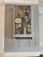
But, now that I have the chassis in hand, it is rather apparent that there really isn't room to fit an internal SMPS power supply module comfortably. Certainly not with adequate separation between the high-frequency switching magnetics and the audio circuitry for my taste. Here's a pic of the bottom panel with a Meanwell RSP-200 module for scale (not that I would choose an RSP-200 for this, it's just what I happened to have laying around). By the time one includes a filtered IEC jack at the rear, power switch at the front (yes, I personally do still consider a front panel power switch as mandatory), and a filter board, it's just plain too tight. Even with a smaller module like the Meanwell HRP-150 series.
OK, so on to the backup plan... power supply housed in a separate chassis. Fine by me, and retains the benefit of electromagnetic isolation from the audio circuitry. But it would require a matching chassis to stack with the amp itself, and darn it if this lovely V-FET chassis isn't a custom width (290mm) that doesn't seem to match the standard modushop offerings. So that might mean I have to order a full-custom modushop chassis... this is getting more expensive my the minute.
If there is interest from others, and it helps dilute the price, I may still pursue a customized modushop chassis with dimensions sized to stack neatly under the V-FET amp... same XY footprint, Z height close to the Slimline 1U series. 10mm aluminum front panel with customization to have a "V" cut motif matching the V-FET front panel, and a large diameter hole for the requisite illuminated-ring push button power switch. But, I don't yet know what this will cost, so there's a chance I won't pursue it if it's too expensive. I'd be very disappointed to give up and live with the brick though.
Hmm, so on a purely aesthetic basis, I want to have either an internal or secondary-chassis-enclosed power supply. There's nothing wrong with the Meanwell brick from an electrical standpoint, and I have no compunction about using an SMPS to power this amp... the magnetic field isolation benefit of physical distance is actually a nice benefit. I just personally don't like power bricks cluttering up the floor behind the stereo rack. And I feel a nice amp like this is deserving of something a little more sophisticated (at least in terms of cosmetics). For others, the SAF may weigh in this direction as well, though I imagine many won't mind the separate brick.
But, now that I have the chassis in hand, it is rather apparent that there really isn't room to fit an internal SMPS power supply module comfortably. Certainly not with adequate separation between the high-frequency switching magnetics and the audio circuitry for my taste. Here's a pic of the bottom panel with a Meanwell RSP-200 module for scale (not that I would choose an RSP-200 for this, it's just what I happened to have laying around). By the time one includes a filtered IEC jack at the rear, power switch at the front (yes, I personally do still consider a front panel power switch as mandatory), and a filter board, it's just plain too tight. Even with a smaller module like the Meanwell HRP-150 series.
OK, so on to the backup plan... power supply housed in a separate chassis. Fine by me, and retains the benefit of electromagnetic isolation from the audio circuitry. But it would require a matching chassis to stack with the amp itself, and darn it if this lovely V-FET chassis isn't a custom width (290mm) that doesn't seem to match the standard modushop offerings. So that might mean I have to order a full-custom modushop chassis... this is getting more expensive my the minute.
If there is interest from others, and it helps dilute the price, I may still pursue a customized modushop chassis with dimensions sized to stack neatly under the V-FET amp... same XY footprint, Z height close to the Slimline 1U series. 10mm aluminum front panel with customization to have a "V" cut motif matching the V-FET front panel, and a large diameter hole for the requisite illuminated-ring push button power switch. But, I don't yet know what this will cost, so there's a chance I won't pursue it if it's too expensive. I'd be very disappointed to give up and live with the brick though.
Attachments
Hmm, so on a purely aesthetic basis, I want to have either an internal or secondary-chassis-enclosed power supply. There's nothing wrong with the Meanwell brick from an electrical standpoint, and I have no compunction about using an SMPS to power this amp... the magnetic field isolation benefit of physical distance is actually a nice benefit. I just personally don't like power bricks cluttering up the floor behind the stereo rack. And I feel a nice amp like this is deserving of something a little more sophisticated (at least in terms of cosmetics). For others, the SAF may weigh in this direction as well, though I imagine many won't mind the separate brick.
But, now that I have the chassis in hand, it is rather apparent that there really isn't room to fit an internal SMPS power supply module comfortably. Certainly not with adequate separation between the high-frequency switching magnetics and the audio circuitry for my taste. Here's a pic of the bottom panel with a Meanwell RSP-200 module for scale (not that I would choose an RSP-200 for this, it's just what I happened to have laying around). By the time one includes a filtered IEC jack at the rear, power switch at the front (yes, I personally do still consider a front panel power switch as mandatory), and a filter board, it's just plain too tight. Even with a smaller module like the Meanwell HRP-150 series.
OK, so on to the backup plan... power supply housed in a separate chassis. Fine by me, and retains the benefit of electromagnetic isolation from the audio circuitry. But it would require a matching chassis to stack with the amp itself, and darn it if this lovely V-FET chassis isn't a custom width (290mm) that doesn't seem to match the standard modushop offerings. So that might mean I have to order a full-custom modushop chassis... this is getting more expensive my the minute.
If there is interest from others, and it helps dilute the price, I may still pursue a customized modushop chassis with dimensions sized to stack neatly under the V-FET amp... same XY footprint, Z height close to the Slimline 1U series. 10mm aluminum front panel with customization to have a "V" cut motif matching the V-FET front panel, and a large diameter hole for the requisite illuminated-ring push button power switch. But, I don't yet know what this will cost, so there's a chance I won't pursue it if it's too expensive. I'd be very disappointed to give up and live with the brick though.
I would be inclined to get a 2u chassis for aesthetic reasons. I would also get a chassis that is narrow enough that the fins are exposed on each side to encourage convection. With the power supply underneath and the fins elevated might even improve cooling.
Drop all boards as low as can go on the heatsinks and hang the supply from the top panel?
That might work well.
Drop all boards as low as can go on the heatsinks and hang the supply from the top panel?
Could be really challenging to get that wired up and assembled. I would probably go the opposite way, push the output stages upwards on the heatsink and keep the SMPS module at the bottom. But, I think it would still be an awkward fit.
I would be inclined to get a 2u chassis for aesthetic reasons. I would also get a chassis that is narrow enough that the fins are exposed on each side to encourage convection. With the power supply underneath and the fins elevated might even improve cooling.
Yes, something a bit taller than the 1U height would likely look a bit more proportionate with the amp chassis.
As it was mentioning here before, there is a big difference (more than usual) between in temperature in vfet casing and the nearby aluminum angle. Anything we can do to improve it? These are hottest transistors I see in Nelson’s designs so far, kinda scary.
What's your opinion PKI: Nelson did, or did not, make a mistake here?
I very much doubt he did, just that elevated level of anxiety taking int account the nature of the transistors 🙂
What temps are you seeing?
Need to get batteries for my thermometer, but for now it is 2-3 secs in our Pass units haha.
BTW top modern IRF 250 transistors a substantially cooler.
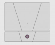
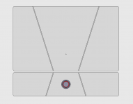
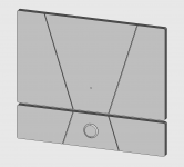
Did up a quick 3D sketch for a potential PSU chassis front panel concept, shown here stacked beneath the amp front panel for the visual. The panel could be installed either right side up to match the V angles on the amp, or inverted depending on preference. The first three are with a slightly smaller EAO power button, the 4th is with my original choice of AV25 (alas TE's step file doesn't show the illuminated ring).
These ones show a 65mm high front panel, chosen for aesthetics, but will likely need a slightly different height in order to work with an economical side extrusion - TBD. Another thought that crossed my mind is that although I intend to use it with SMPS modules only, some others might like to order a chassis which can fit an appropriate toroidal + linear supply caps, so it might be good to leave enough interior Z height for that.
And of course, I still need to cost this out and see if it's palatable or not...
Attachments
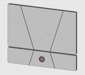
I like it. For what is worth, I think the "inverted" V looks much better than the parallel version.
Did up a quick 3D sketch for a potential PSU chassis front panel concept, shown here stacked beneath the amp front panel for the visual. The panel could be installed either right side up to match the V angles on the amp, or inverted depending on preference. The first three are with a slightly smaller EAO power button, the 4th is with my original choice of AV25 (alas TE's step file doesn't show the illuminated ring).
These ones show a 65mm high front panel, chosen for aesthetics, but will likely need a slightly different height in order to work with an economical side extrusion - TBD. Another thought that crossed my mind is that although I intend to use it with SMPS modules only, some others might like to order a chassis which can fit an appropriate toroidal + linear supply caps, so it might be good to leave enough interior Z height for that.
And of course, I still need to cost this out and see if it's palatable or not...
No.3 looks nice, but I just got back and got to take a look at the case: so tiny and cute! Much smaller than I imagined! I will keep the look as is, will be a contrast powering the 220L speaker cabinet and the SMPS will disappear 'back there' somewhere.
- Home
- Amplifiers
- Pass Labs
- DIY Sony VFET Builders thread