not shure, but in case I want to make a classic transformer-CRC supply:
I already have a 27-0-27V 200VA Torroid.
I know that we use (at least) 300VA for normal FW iterations, but this one dissipating a little less, so 200 VA should be ok, right??
...
I built an amp (2SK82 -2SJ28 SE Amp) with a very similar output stage and I used an Antek 400VA power transformer. It was the AS-4218, which I reused from my 193V L'Amp build. I connected the 2 x 18V secondaries in series to a CLC power supply and ended up with about 45V under load. My 2SJ28s are operating at 18.5V, 1.5A.
The interesting thing is the transformer runs quite hot. Not warm, but hot. I can hold my finger on metal mounting plate for maybe 5 or 6 seconds. I haven't measured the temperature yet. If I was not reusing a transformer, I would have bought a bigger transformer. When I was using it in my choke loaded 2SJ28 L'Amp, it was running at two channels of 21V at 2A and it was cool. Now at 2 x 45V at 1.5A, it is very hot. 85 watts compared 135 watts on a 400VA transformer.
Any newsReceived screws ?
yup, just yesterday
all finished and singing nicely
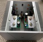
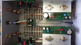
#19 is up and running! Thank you everyone for making it possible!
The most difficult part was to put this chassis together... with my sausage fingers
The most difficult part was to put this chassis together... with my sausage fingers
Attachments
#044 alive
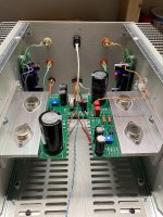
Warming up and sounding good with some Jonny Lang on my little bedroom test system. I mounted both of my FE boards with the -D/+D up. Reason being... to be able to...with some quick easy soldering....move the wire straight to the RCA jack to directly drive the OS from an external linestage with enough gain / swing, just for experimentation sake if I wanted to in the future. Mr. Pass mentions this as a possibility in the article.
Warming up and sounding good with some Jonny Lang on my little bedroom test system. I mounted both of my FE boards with the -D/+D up. Reason being... to be able to...with some quick easy soldering....move the wire straight to the RCA jack to directly drive the OS from an external linestage with enough gain / swing, just for experimentation sake if I wanted to in the future. Mr. Pass mentions this as a possibility in the article.
Attachments
I would enjoy giving the BA3 FE a go in driving this amp
You'll probably have to create a new PCB layout which has the correct form factor and mounting hole positions, to properly interface to the VFET heatsink and VFET chassis.
You'll also have to change the circuit design, at least a little bit, because the original BA3 used and exploited dual-rail power supplies, whereas the VFET is a single rail supply. So for example you have absolutely no choice, you must jettison the BA3's DC coupled input, and then design an alternate arrangement. A few details like that.
You may or may not want to make your new BA3 board compatible with both P-VFET amp channel boards, the ones shipped this week, and ALSO compatible with the N-VFET amp channel boards that won't get shipped until summertime. If so you'll probably decide to wait and see just what the N-VFET amp is, and what it needs, and how you can interface to it. Because if you guess wrong, you have to revise your PCB layout and scrap the Toshiba JFETs that were on the rev 1 boards.
Bouncing on william2001 while waiting for my parts to arrive, as I have some similar thinking since some time in fact... while also wanting to keep things as original as possible...
I remember that this negative phase thingy gave me some headache especialy as I run the B1K differently from what is intended - I managed to understand it but it is quite a few months back, needing some refresh please if possible...
Thinking out loud...
Suppose you have a source with enough voltage output to drive your LS loud enough through the VFET power board without the FE board gain. Suppose then you want to try the VFET board direct, that is without any front end (well noting that the existing standard FE is also conveniently inverting phase and not just providing gain). Is my following understanding correct?
If you wire the LS terminal exactly as intented /as in Papa's instructions (eg inversing LS connections INSIDE the chassis), and you are running a "normal source without phase inversion capability, one that maintains always absolute phase", then all you would need to do to get both correct absolute phase and enjoyable "negative H2" out of the VFET amp section... would be to inverse the LS cables at the terminals (externaly). That is in fact equivalent to connecting the LS... as they would be in fact in an usual amp.
Is that right?
Asking because, depending on the loudness we will get in real life, my calculation tend to show that I shall already get reasonably loud on usual material without FE. Hence mounting a simple switch that would enable me to bypass the existing FE - in hope that this "pure direct mode" would sound even better. I see no danger as, if I am not mistaken, I can easily get the intented result re sonic signature (absolute polarity and negative H2) while the VFET power modules do have a very high input impedance and DC input protection (the input cap) enabling probably to connect directly a coventional source without dynamic or frequency response downsides. Then, IF really wanting to go party mode I could still switch back in the FE module, getting then more oomph (gain, hence output power), but admittely then - if I am lazy to do anything and I don't reverse the LS cables- with inverting absolute phase and positive H2 in that specific case. But then, if a party, who cares LOL!
My modest FE module tweak could hence be a clever and discrete simple quality switch (say one per channel for easy implementation) somewhere hidden at the underside of the chassis, bypassing or not the FE (while everything is switched off)
Does that make sense?
Claude
EDIT: ths switch could be a simple DPDT "ON- (ntothing) - ON" per channel, switching both lines of a RCA connection in one go, between FE and direct...
Last edited:
yup, just yesterday
all finished and singing nicely
Bravo Adason!
Hope next week or in 10 days and I can make sing VfetSE as well.
Dream to play sublime acoustic orchestral records
and tests amplifier "limits" on fortissimo moments for example
John Rutter The Ultimate Collection - YouTube

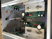
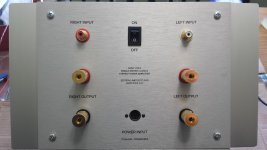
Amplifier 047 is alive and playing some very sweet music on a pair of Monitor Audio bronze on the kitchen table. Will be hooking it up to my Elsinor mk3 soon. Thanks for this wonderful amp Nelson and the whole team. A few pics for the porn addicts....
Attachments
The front end cards that don't use an Edcor transformer, have a slide switch which lets you select whether you want inverted, or non-inverted signal polarity. The ones which do have an Edcor can output either polarity, merely by swapping (or not swapping) the transformer secondary wires.
The SIT output stage has been designed to accept its signal from different styles of input stages. See Mark Johnson's designs and others. If your preamp will drive an F4 , it will likely drive the SIT output stage.
Pay attention to the fact that the input to Nelson's P CH SIT output stage is normally from the -D output of the preceding buffer/gain stage. And, very importantly, the input RCA grounds will be tied to the chassis ground unless your amp breaks that shield ground loop.
, it will likely drive the SIT output stage.Pay attention to the fact that the input to Nelson's P CH SIT output stage is normally from the -D output of the preceding buffer/gain stage. And, very importantly, the input RCA grounds will be tied to the chassis ground unless your amp breaks that shield ground loop.
Last edited:
- Home
- Amplifiers
- Pass Labs
- DIY Sony VFET Builders thread