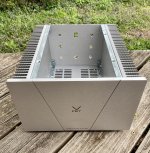
My chassis kit arrived this morning, number 028, parts kit due this afternoon.
How odd to be so happy about rainy days this week.
How odd to be so happy about rainy days this week.
Chassis arrives tomorrow, couldn’t help myself. I had to start.
Monday many Diyers have received chassis for his electronic parts kits.
Let's see time line with the first fully assembled working units.
Funny surprises can happen, let's start the show


That looks great!!!
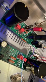
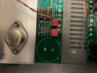
So, for those of us waiting on our kits... the entire input stage is soldered to the filter and to the inputs of the output stage. For those looking into the future to test different input stages, there are no means to make these changes without rethinking a bit connectors?
Thanks for the feedback.
So, for those of us waiting on our kits... the entire input stage is soldered to the filter and to the inputs of the output stage. For those looking into the future to test different input stages, there are no means to make these changes without rethinking a bit connectors?
Thanks for the feedback.
@ Codyt
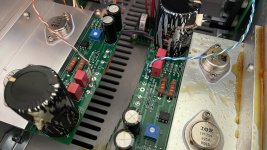
Jfets with little metal heatsink hats 😉 Well done wiring!
Please more photos of the working amplifier..
and description about sound and speakers used in the test ? 😀
Jfets with little metal heatsink hats 😉 Well done wiring!
Please more photos of the working amplifier..
and description about sound and speakers used in the test ? 😀
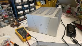
Breathing a sigh of relief. Everything fired up great. Just as adason said, I was getting around 15v with pots at half way mark. Adjusted up to 19v and will see what kind of change an hour of warmup brings.
Will listen to it soon, but I have nothing but great things to say about this kit. Well considered and looks incredible 🙂
Will listen to it soon, but I have nothing but great things to say about this kit. Well considered and looks incredible 🙂
Attachments
That looks great!!!
So, for those of us waiting on our kits... the entire input stage is soldered to the filter and to the inputs of the output stage. For those looking into the future to test different input stages, there are no means to make these changes without rethinking a bit connectors?
Thanks for the feedback.
Rafa, that’s a good question. I was considering using 2-position terminal blocks for each of the input, output and power entries. The holes on the input boards were just a little too wide to fit the terminal blocks I had. It’s possible you could bend to make fit or find a wider terminal block(?).
Breathing a sigh of relief. Everything fired up great. Just as adason said, I was getting around 15v with pots at half way mark. Adjusted up to 19v and will see what kind of change an hour of warmup brings.
Will listen to it soon, but I have nothing but great things to say about this kit. Well considered and looks incredible 🙂
Its actually other way around. It draws more current when you set lower voltage on the source. Set 20, its very stable.
I just noticed that nothing seemed to move after warmup. Set it to 20v, and gonna see if she plays music
And did you supply your own blue LED? Mine looks to be red! Unless it's just a red lens or something...
Seems like blasphemy on a Pass designed amp!
Seems like blasphemy on a Pass designed amp!
..and gonna see if she plays music
Joan Jett "I Love Rock N Roll" on Vimeo
What audio source and preamplifier ?
 Thanks for sharing
*ALERT*
Please check the silkscreen / polarity orientation of your C1 capacitors in OS. Mine has discrepancy from the one in the documentation and Jim’s (6L6) build. I know this first hand...
Please check the silkscreen / polarity orientation of your C1 capacitors in OS. Mine has discrepancy from the one in the documentation and Jim’s (6L6) build. I know this first hand...
Attachments
Oh No!!!! Those beautiful Mundorfs! 🙁
Thank you so much for posting. Hoping everyone sees this and makes note.
Thank you so much for posting. Hoping everyone sees this and makes note.
Oups, that is unfortunate. Hope you have some spare in your toolbox to quickly fix that.... all looking forward to the first impressions! Although we all know it will be very good!!
@ Codyt
Oh no so baadz!!
Feel sorry such high quality Mundorf caps are exploded and all "juice" around
Anyway Codyt You are the Hero 🙂 Thanks for sharing
Oh no so baadz!!
Feel sorry such high quality Mundorf caps are exploded and all "juice" around
Anyway Codyt You are the Hero 🙂 Thanks for sharing
Has anybody else been able to confirm the polarity of their OS boards? Hopefully it’s an isolated instance. I’m guessing Adason’s silkscreen was accurate, as I say his caps were orientated opposite mine.
Is the PCB silkscreen wrong?
What a mess.....how do you clean that up?
Hopefully the VFETs survived.
Also dangerous to be a "forerunner"......
Now that this has happened.....how did the explosions sound?
What a mess.....how do you clean that up?
Hopefully the VFETs survived.
Also dangerous to be a "forerunner"......
Now that this has happened.....how did the explosions sound?
Thanks for pointing this out. One of my output caps was backwards. The silkscreen appears different between the two channels.Please check the silkscreen / polarity orientation of your C1 capacitors in OS. Mine has discrepancy from the one in the documentation and Jim’s (6L6) build. I know this first hand...
- Home
- Amplifiers
- Pass Labs
- DIY Sony VFET Builders thread