Perfect, that’s good to know. I centered mine before installing, as I was unclear if they were shipped with correct adjustment.
Center position will only give you ~14 volts.


Tell us how it sounds and whoever wins NP will confirm and voila.. you're the winner😉
No evaluation means incomplete
No evaluation means incomplete
Last edited:
Challenge game show of 100% complete SE Vfet amplifier build is still open.
First five quickest Greedy Boyz titles are to winGood luck!
If this were a competition, I’d be that guy in the back trying to keep up (with his eyes closed) 😀
Attachments

My kit is in transit eta 30th April. So mine will not be the first build but Im happy that I won a slot. And this vill not be the last FW I build 🙂
Regarding solderin temp. Are you using around 600F. If that is correct Im soldering way to hot. My station is at 700C
@ kbergsson
I hope you mean 700F!?
🙄
naah
what's one letter of difference, between friends
🙂
Yes sorry I live in a celsius world. So typing C for temp feels natural 🙂@ kbergsson
I hope you mean 700F!?
🙄
Last edited:
For a nice round number, 700F works wonderfully for me using a fairly standard 63/37 solder. I use a larger mass tip and/or crank up the temperature a bit when soldering to a large ground plane or a big part like a speaker binding post with a relatively large mass.
If you're using lead free solder or a fancy silver solder... YMMV.
Enjoy!
If you're using lead free solder or a fancy silver solder... YMMV.
Enjoy!
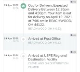
My boards are now complete and waiting for the chassis to arrive. Hopefully tomorrow.
I did run into a minor hiccup. My parts kit included two extra 100Ω resistors for the output stage, and only a single 100kΩ resistor. Fortunately, I was able to locate a spare 100k resistor in my spare parts stash to complete the build. If others run into similar issues, then we may wish to bring this to the attention of the diyAudio store. If it was just me, then no worries.
I did run into a minor hiccup. My parts kit included two extra 100Ω resistors for the output stage, and only a single 100kΩ resistor. Fortunately, I was able to locate a spare 100k resistor in my spare parts stash to complete the build. If others run into similar issues, then we may wish to bring this to the attention of the diyAudio store. If it was just me, then no worries.
Can any of the lucky people who have a kit tell me what the p/n of the Meanwell smps is
please. NP said it was the quietest one available for the job. Im having to build my own copy and I want to use the same if poss. Thanks
please. NP said it was the quietest one available for the job. Im having to build my own copy and I want to use the same if poss. Thanks
@Zeta4, it's no surprise that your question has been asked (and answered) before. Take a look at post #537 of the DIY Sony VFET pt 1 thread.
The MeanWell PSU supplied with the VFET parts kit is the GST160A36-R7B. This has a mini 4-pin DIN connector.
- Home
- Amplifiers
- Pass Labs
- DIY Sony VFET Builders thread