Off course...Please can you post here the pcb and firmware?
This is the source code, you may need to improved ...
PHP:
#include <12F675.h>
#fuses INTRC_IO,NOWDT,PUT,NOPROTECT,NOCPD,NOMCLR,BROWNOUT
#device adc=8
#use delay(clock=4000000)
#define GP0 PIN_A0
#define GP1 PIN_A1
#define GP2 PIN_A2
#define GP3 PIN_A3
#define GP4 PIN_A4
#define GP5 PIN_A5
//This function indicates blink error codes
void ledctrl(int display){
int a=0;
while(a<display){
delay_ms(500);
output_toggle(GP5);
a=a+1;
}
delay_ms(1000);
}
float dc_det, oc_det, temp_det, temp_value;
void main(){
for(;;){
//With this we avoid erroneous trips by clipping
delay_ms(100);
//Initialize ADC
setup_adc(adc_clock_internal);
setup_adc_ports(all_analog);
//Read conditions DC detector
set_adc_channel(0);
dc_det = read_adc();
//Read conditions overload detector
set_adc_channel(1);
oc_det = read_adc();
//Read amplifier temperature
set_adc_channel(2);
temp_det = read_adc();
temp_value = 1.955032 * temp_det;
//Detect if the DC output
if(dc_det < 254){
output_low(GP4);
output_low(GP5);
ledctrl(4);
}
//Detect if the amplifier is overloaded
else if(oc_det < 254){
output_low(GP4);
output_low(GP5);
ledctrl(6);
}
//Detect if there overheat
else if(temp_value >= 70){
output_low(GP4);
output_low(GP5);
ledctrl(8);
}
//If all goes well, activate the relay
else{
if(input(GP3)){
output_high(GP5);
}
else{
ledctrl(5);
}
output_high(GP4);
}
}
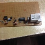
}Attached files of simulation in Proteus, the HEX file and the PCB real scale.
Greetings
Attachments
Last edited:
This code works good, I meant that someone with more experience than me, could improve it ;-)Thank you but i can't improve the code🙁
I know the way to load the code on chip only🙁
In post 85 if any emiter resistor draws too much current, the transistors 2n5401 or 2n5551 turn on, sending a signal out A that too much current is flowing. The diodes summing the current of the 4 emiter resistors is a good trick. Makes an "or" circuit of the 2n5401 and 5551. Some circuitry is missing between A the overcurrent detection output, and C the disconnect relay driver. Probably there is also a power on silence circuit to hold the output relay out, as well as a possible heat sink overheat detector to trip on fan failure.
I'm not that thrilled about interrupting DC current with hard contact relays. For one thing DC tends to weld the contacts together, especially in 4 transistor amps like this one that can source 20 to 40 amps. For another thing there are constantly threads on diyaudio about sound stopping at the relay in old receivers etc. If the relay contacts are not gold plate then they oxidize after several years and stop current. And gold plate contacts are the wrong contact material for currents greater than 50 ma.
I thought your back to back mosfet circuit you posted previously was okay, but it opens the speaker path. I like Michael Bean's idea, to open up the rail voltage with a MOSFET if a DC on speaker or other fault is found . That way, if one OT shorts out due to a speaker or heat fault and causes DC on the speaker, operning the rail MOSFETs might save the other 7 or 9 output transistors, which otherwise could cross conduct because of the heat and still blow up. That's my objection to triac crowbars, they damage the overstressed $5 apiece output transistors. Besides the triac melting itself off the PWB in my amp instead of tripping the mains breaker.
I'm building a protection circuit using some $2 Fairchild fdp52n20 mosfets with a 52 amp rating and .04 ohm resistance. I've held up finishing it for a year because for reliability the 1 microamp signal from the (pamasonic opto IC) fet driver current to gate and source should be soldered, but the drain & souirce legs should be crimped to the rail wires to withstand 30 amps without overheating and melting the solder out. I don't etch circuit boards, I don't like dumping ferric chloride down the drain or on the ground. But, yesterday I figured out I can saw the middle out of a dead PCAT power supply board, with the heat sink, and have nice etched lands soldered to the MOSFETS that I can solder to or drill through for 10 ga wire, both. The mosfets need that big PCAT heat sink anyway at the 22 amps my PV1.3k delivers in the 2 ohm load senario. Or 44 amps for both channels.
I just so far have the built DC detector from the PV-1.3k triac crowbar tripping the fault latch (a 74hc74 IC in my board) I'd been monkeying with opto isolators reading the voltage across the fdp52n20 to detect overcurrent, then setting the fault latch. A third input could be the thermal switch on the heat sink of the PV1.3k to detect fan failure.
The nice thing about summing the 8 emiter resistor overcurrents the way this circuit post 85 is shown, the overcurrent signal is already ground referenced. Reading the rail fets, i have to use an optoisolator to bring the two overcurrent signals from both rails back to a single point (the speaker ground) Unfortunatley the PV-1.3k speaker ground flies around with the music, so I'm still probably going to use optoisolators, and a separate "logic" ground for the fault circuit close to the case and safety ground voltages.
The one thing I see wrong with the overcurrent detect in post 85, one intantaneous overcurrent will trip the transistors. I'd put in a capacitor on the base of the 2n5551 and 5401 to slow things down a little bit where it took 2 or three overcurrent cycles before the overcurrent fault went off.
Last edited:
Hello Indianajoe
greetings and many thanks for your detailed inputs so many protections
around the 21 century protection is great i want to keep things simple
cheap cheap AC current sensor will work for sure for overload protection
i see a small problem in all circuits when overload protection is triggered
the relay keeps going ON and OFF can this be rectified or am i chasing a
ghost practically i an trying every schematic i find surely something will
work thanks for replying
warm regards
Andrew
I'm sending the "DC voltage present on speaker" signal through optoisolators (since the ground flies around with the rail voltages on Peavey equipment) to a 74HC74 latch, powered by a separate wall transformer (installed in the amp case). That way the fault cricuit goes on and stays on until power is turned off by the roadie (or me) . A transistor driven by the 7rHC74 drives a fault LED visible through the front vent slits, The green side of the LED drives the the FET driver IC's to turn on rail current.
Current sensor transformers on the outputs are cheap in bulk, Peavey uses them in the CS800s amp, but individually the distributors want >$10 for them.Those I don't know if the output is sensitive enough to produce .6 v for a transistor base. I don't like the Hall effect IC boards for current sensing, at $9 each + $9 freight (not sold by general distributors). On 22 amps expected speaker current , the pins or solder holes of the hall effect sensor board aren't big enough for 10 ga wire.
Optoisolators are about $.50 or less each, I've got about ten of them in my circuit for each channel. At normal 22 amps the fdp52n20 MOSFET in the supply rail between capacitor and output transistors will drop .88 v, so to set off an optoisolator at 1.2 v the circuit would be drawing 30 amps from the rail, pretty **** sensitive current detection IMHO. Your amp may need a lower current trip point with less than the 5 MJ15025 output transistors my PV.1.3k has.
Last edited:
Hello Indianajo
greetings yes you are right your protection is very good high tec is there
any way my problem can be solved no need to buy current transformers
i wind it at home
warm regards
Andrew
greetings yes you are right your protection is very good high tec is there
any way my problem can be solved no need to buy current transformers
i wind it at home
warm regards
Andrew
Does post85 work?
I would put the relay in the collector as the load and connect emitter to power ground.
No I wouldn't.
I would add an extra transistor. This second transistor becomes the "switch" and must run saturated, i.e. Ib:Ic ~ 1:10
Then the existing transistor drives the base of the switcher.
I would put the relay in the collector as the load and connect emitter to power ground.
No I wouldn't.
I would add an extra transistor. This second transistor becomes the "switch" and must run saturated, i.e. Ib:Ic ~ 1:10
Then the existing transistor drives the base of the switcher.
That top sch works.
But I would move Z1 to the other side of Q2, or change it to a grn LED, also between Q2 & Q3.
I don't understand the purpose of c3.
R5 is not required.
It just increases the leak in parallel to the timing capacitor. It's a very crude way of increasing the delay.
But I would move Z1 to the other side of Q2, or change it to a grn LED, also between Q2 & Q3.
I don't understand the purpose of c3.
R5 is not required.
It just increases the leak in parallel to the timing capacitor. It's a very crude way of increasing the delay.
Hello
greetings just want to know in overload protection is a latching circuit best
i mean when speaker wires are shorted relay remains in off state till 12 v dc
is cut off its simple overload which senses emitter drop voltage when overload
warm regards
Andrew
greetings just want to know in overload protection is a latching circuit best
i mean when speaker wires are shorted relay remains in off state till 12 v dc
is cut off its simple overload which senses emitter drop voltage when overload
warm regards
Andrew
Hello AndrewT
greetings just an ordinary 12 volt relay
warm regards
Andrew
A triac is used because once it fires, it latches the SSR OFF. If it did not latch (as would be the case for example if a normal Opto wee used), it would cycle on and off
do you have schematic using triac to avoid the above problem or is latch circuit better
once overload occurs relay remains energised its very crude protection but will save amplifier
The latch off is good.
NX discusses this and of course Mooly's Thread on SSR.
But the latch drops out when the current drops below threshhold.
I use a 555 timer.
It pulls to OFF, when triggered and then restarts the timer delay before power comes back on.
If the fault is still detected, the timer ON after delay is overridden and the power does not come back on.
If the fault were cleared, then power would cycle in 5second periods.
- Home
- Amplifiers
- Solid State
- diy short circuit protection