I use a 555 timer.
It pulls to OFF, when triggered and then restarts the timer delay before power comes back on.
If the fault is still detected, the timer ON after delay is overridden and the power does not come back on.
If the fault were cleared, then power would cycle in 5second periods.
It pulls to OFF, when triggered and then restarts the timer delay before power comes back on.
If the fault is still detected, the timer ON after delay is overridden and the power does not come back on.
If the fault were cleared, then power would cycle in 5second periods.
I use a 74HC74 latch. It is sensitive enough to be latched by an optoisolator phototransitor on the set pin. It is powerful enough to drive a transistor which drives a green LED in series with the photoemitter diode of a Panasonic FET driver. Thes need 10 ma. The opposite Q drives the red LED only via a tansistor. It is cleared by the power up reset pulse after the unit is turned on - an RC time constant driving a 2n7000 FET.
The channel LED goes red if a fault is detected, the rail capacitors disconnect from the output transistors as the 74hc74 sets. Hopefully 9 of the 10 output transistors are saved after one fails and puts out DC. Or another fault besides DC on output occurs. The optoisolators from fault detection can be wire or-ed to set the flipflop on a number of conditions. DC on speaker output for too long, heat sink too hot due to stuck fan, maybe overcurrent on the rail fets.
I don't want this amp to cycle all night - I leave my amps on for hours at a time without a roadie watching. Fault occurs, light comes on, one channel goes dead. Other channel can soldier on if the fault doesn't affect it. Most common fault is 1/4 phone plug to speaker pulled out, of course. My speakers use those, even if the amp end is changed to speakons or something.
Hello indianojo
greetings thanks for replying is it possible to share your schematic for
me to try for my PA amp if its possible
warm regards
Andrew
greetings thanks for replying is it possible to share your schematic for
me to try for my PA amp if its possible
warm regards
Andrew
Sorry, the schematic is on paper with pencil. I use Linux op system on a PC; the GEDA schematic drawing utility from ubuntu doesn't have a lot of the components I used. Since this is digital, analog, and opto, I'm not sure anything would. TinyTI program on Win 7 looked promising but that op system was installed by the laptop vendor and was killed for me by microsoft with "updates" 6 weeks after purchase. Used computers never come with a windows source disk that matches the microsoft number on the back. Not even the PCs my brother gives me come with a Win source disk. So it is all Ubuntu Linux around here, and wiring is done point to point with a soldering iron instead of board layout program.
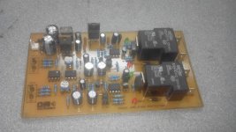
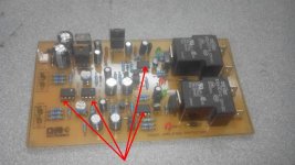
I ask again for schematic and pcb....Finished protection system amplifiers, has Power On Delay, Protection and Protection DC short circuit in the output OCP.
Finished protection system amplifiers, has Power On Delay, Protection and Protection DC short circuit in the output OCP.
Are you sure?simple latch circuit😉
yes thimios very sure c vedio
https://www.facebook.com/andrew.lebon.73/posts/558939094262535?notif_t=like
https://www.facebook.com/andrew.lebon.73/posts/558939094262535?notif_t=like
Hi, Z1 avoid immediate activation of the relay, an LED could also function as limiting, but I have not experienced.That top sch works.
But I would move Z1 to the other side of Q2, or change it to a grn LED, also between Q2 & Q3.
I don't understand the purpose of c3.
R5 is not required.
It just increases the leak in parallel to the timing capacitor. It's a very crude way of increasing the delay.
The C3 is to ease the burden of the relay (optional).
The R5 avoids mis-tripping (optional).
To increase the timing, rather modify the R2 instead of the capacitor ...
Cheers...
35 days for a response.Hi, Z1 avoid immediate activation of the relay, an LED could also function as limiting, but I have not experienced.
The C3 is to ease the burden of the relay (optional).
The R5 avoids mis-tripping (optional).
To increase the timing, rather modify the R2 instead of the capacitor ...
Cheers...
Have you been ill?
I would not like to wait 35days for my Doctor to respond.
I have no constant internet connection, I guess your doctor have, but I doubt consult your doctor from Internet ...35 days for a response.
Have you been ill?
I would not like to wait 35days for my Doctor to respond.

The overload detection is still under development but the other parts are pretty much the conventional solutions.
The signal source on the left top is just for simulating the amplifier output stage
with the PS + emitter resistor (0R18) + the load as a resistor (3.2 in this case).
If anyone has advices to the overload detection please do not hesitate to share your thoughts! 🙂
The signal source on the left top is just for simulating the amplifier output stage
with the PS + emitter resistor (0R18) + the load as a resistor (3.2 in this case).
If anyone has advices to the overload detection please do not hesitate to share your thoughts! 🙂
Hi!
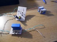
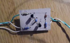
I built it on paper "PCB"... 🙂
All the features are working great and I just started to test the overload section deeper.
The first test setup was a properly scaled voltage devider (1k8 instead of 0R18 emitter resistor and 10k instead of 1R dummy load etc...).
I only drive this with a DC supply yet just to check the current levels where the protection is activeted.
Its clear that the R-D member in the overload detector works as well, check out the "simulated" results:
That looks great so far nevertheless I dare not to test it on my hardly built amplifier... 🙂
Does anybody have any idea how to test it in action but without risking the output stage..?!
I built it on paper "PCB"... 🙂
All the features are working great and I just started to test the overload section deeper.
The first test setup was a properly scaled voltage devider (1k8 instead of 0R18 emitter resistor and 10k instead of 1R dummy load etc...).
I only drive this with a DC supply yet just to check the current levels where the protection is activeted.
Its clear that the R-D member in the overload detector works as well, check out the "simulated" results:
- Rload = 0R -> Imax = 3.3A
- Rload = 1R -> Imax = 3.3A
- Rload = 2R -> Imax = 4.7A
- Rload = 3R -> Imax = 9.4A
- Rload = 4R -> no limit (Uout-max = 55V)
That looks great so far nevertheless I dare not to test it on my hardly built amplifier... 🙂
Does anybody have any idea how to test it in action but without risking the output stage..?!
Attachments
There is a "pulsing" test described somewhere that allows one to "see" the current limit as a deflection on a scope.
I think it involves using a sqw through a capacitor to create the short period pulses that do not damage the output stage but do pass very high currents if the stage has a good current capability.
I wonder if ESP has something on this.
I have a feeling that Pass first described this test.
I think it involves using a sqw through a capacitor to create the short period pulses that do not damage the output stage but do pass very high currents if the stage has a good current capability.
I wonder if ESP has something on this.
I have a feeling that Pass first described this test.
- Home
- Amplifiers
- Solid State
- diy short circuit protection