No.
That would leave a high current for a long duration. That will blow up your output stage.
You need an output stages that can safely pass a long duration DC current
AND
pass a short duration pulse that can be double or even ten times the safe DC current.
eg a 100W into 8ohms amplifier passes a 5Apk current into a 8r0 test load.
That is a medium duration current pulse. The amplifier must survive this.
The protection circuit must allow this to pass. It is a valid audio signal passing to a valid audio load.
Can the output stage survive a 5A DC current continuously passing to a load?
This may require the DC current detection to trigger at a lower current value than the 5A of the previous test condition.
Next consider passing fast changing signals into a reactive speaker load. Typically the peak currents of these transisent (short period pulse) currents can be anywhere from two times to five times the test current into a 8r0 resistive load.
If you want your output stage to pass a 15Apk very short term transient, your detection system must allow that pulse to pass and the output stage should be designed to survive this short term pulse.
Look at the SOA curves in the datasheet. There is an enormous difference between DC SOA and 1ms SOA and 1us SOA.
Transistors can safely pass short period transients that are very much higher than their DC rating.
An amplifier protection system must allow all valid audio signals to pass to all valid audio loads.
That to me means that there are different detection systems that can differentiate between 15Apk for 1us and 2Adc continuous.
Last edited:
An RC filter is a very crude version of DC vs transient pulse discriminator.
It can be made to work adequately well. You will find it in MANY circuits, Crimson & Cyrus use them in protection circuits that are required to pass high transients but able to detect lower DC currents. The output offset detector uses an RC filter. It allows BIG AC pulses to pass and yet detects much lower DC currents.
That would be where the pulse tester would come to your aid. To "see" how the detector protects.
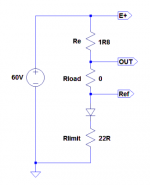
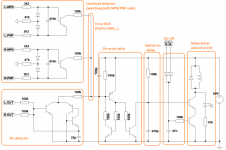
In the meantime I created a pre-test setup simulating the output stage.
Voltage source: amplifier with sinus on the output
Re: NPN emitter resistor (value = 10x in this setup)
Rload: the load (value can be from 0 and should be 10x as well maintainang the voltage divider)
Ref: this is the absolute reference point for the R-D elementin the overload detection cicuit
Diode: for simulating the NPN side
Rlimit: limits the current so the short-cicuit can be simulated as well
I tried it with 100Hz/1kHz sinus and it worked perfectly.
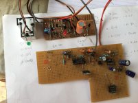
Maybe a bit closer to a real life environment... 😉
Voltage source: amplifier with sinus on the output
Re: NPN emitter resistor (value = 10x in this setup)
Rload: the load (value can be from 0 and should be 10x as well maintainang the voltage divider)
Ref: this is the absolute reference point for the R-D elementin the overload detection cicuit
Diode: for simulating the NPN side
Rlimit: limits the current so the short-cicuit can be simulated as well
I tried it with 100Hz/1kHz sinus and it worked perfectly.
Maybe a bit closer to a real life environment... 😉
Attachments
Last edited:
Hello Cortez
greetings what happens when an overload occurs does the relay go on and off
warm regards
Andrew
greetings what happens when an overload occurs does the relay go on and off
warm regards
Andrew
The switch-on delay (~1s) will be applied in this case as well before going ON again.
With very heavy overload maybe, but with light overload, the relay will turn off, and on almost immediately.
Sajti
I think it is only possible when the load current varies exactly near the switch off current for seconds.
Yeah, I tested it and with a constant sinus around the switching level and the relay turns on/off almost immediately.
short circuit protection
Hello
greetings finally on delay latch is working and overload
warm regards
Andrew😉
https://www.facebook.com/andrew.lebon.73
Hello
greetings finally on delay latch is working and overload
warm regards
Andrew😉
https://www.facebook.com/andrew.lebon.73
Attachments
tem como disponibilizar o projet
 English please.
is there any way make the project
is there any way make the project
Internet robot translation is weird...
"Is there any possibility of providing the project (plans, circuit, schematics, etc.)?"
Hello Cortez
greetings tried your DC detector didnt work on my latch circuit
warm regards
Andrew
greetings tried your DC detector didnt work on my latch circuit
warm regards
Andrew
How did you connect it with your latch?
This one pulls its output (after the 100k) to GND.
Maybe your latch is positive triggered, isn't it?
This one pulls its output (after the 100k) to GND.
Maybe your latch is positive triggered, isn't it?
Hello Cortez
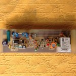
greetings its ok solved my short circuit protection its working 100%
i will try to design a pcb for it and post a working vedio of protection
in action it took a long time but i learnt some new ways to safeguard amps
time permitting will add a solid state relay as mechanical relays contacts
degrade in time
warm regards
Andrew
- Home
- Amplifiers
- Solid State
- diy short circuit protection