Hello
Can someone let me know what is the correct angle from spindle to the arm pivot? I think that is very important to get the correct protractor!
It must be some position, otherwise the arm pivot can move up or further from the spindle and I still get the right overhang measurement.
I think Frank gave me that info to probably I need some explanation.
I put question marks what is not clear. The rest look like OK to me.
Thank you very much!
Greetings Gabor
Attachments
Good morning Gabor,
Just stick to the pivot to spindle distance figure given in my last posting. Then draw a circle (r=291,6mm) around your platter. Now you can place your arm pivot anywhere on that circle, as long as it doesn't interfere with the lid or other parts of the plinth and as long as it looks good to you.
The green line in the drawing is of no importance for the geometry of an arm and has no bearing on the correct choice of protractor. Imagine a prefectly circular turntable plinth and it becomes very clear that you can place your arm anywhere on said r= p to s circle.
A protractor based on Mr. Dennesen's design will give you the correct angle and overhang in one operation, an arc protractor like the one from Ken Willis may need a little more fiddling, but some feel they're getting more precise results. Try both and decide for yourself.
Hi Ron,
Thanks for the kind words.
If you should ever meet me in person, you'll find that "Frank" without the "Herr" or an undeserved academic title is just fine. The only person calling me "Papa" is my 14 year old son 🙂
Ralf!
What's up? How's the last iteration of your awesome arm coming along?
All the best,
Frank
Hello Frank
If I understood right one of the most important to keep the given overhang and use a protractor to get the right angle on the record..
I did tested several (5 or 6) turntable from the outer groove to the inner groove angle and I get from all different angle. Interesting all has S shape 9" tonearm.
To me a bit confusing, supposed to be some rule or something.
I will register and download a protractor and with that I set up the arm (stylus start) angle from the outer groove to the inner groove after the protractor.
I do not have dust cover or any other parts to interfere with.
I will design the plinth after the two arm size.
How I stated earlier I'll use two arm on these deck one 15" and one 12".
One will be at the top another next to the platter like most regular TT has.
Can I use for the 15" the same measurement as for the 12" or I have to calculate that to. If case if have to be calculated I have to ask for help with that to. I ashamed to ask you since you help me more than ever I can thank you! Reason I use two arm because I purchased diferent material for arm wand and I pick the two best.
The protractor will give the angle for the stylus start and that will give the arm pivot to. That is correct?
Thank you very much🙂
Greetings from Toronto
Attachments
Last edited:
Hi,
You need to adjust your cartridge/cantilever for perfect tangency at the null points. Only when using an arc protractor, you are effectively "aligning the arm (angle?) from outer to inner groove", by trying to follow that arc precisely(valid for one eff. l. only!).
Just download such an arc protractor and try it on an existing deck. You'll figure it out...
Send the 15" ers exact eff. l. and I'll send the corresponding numbers again. Or go and download the Elison excel sheet, as suggested.
Have a great weekend,
Frank
Hi Ron,
Thanks for the kind words.
If you should ever meet me in person, you'll find that "Frank" without the "Herr" or an undeserved academic title is just fine. The only person calling me "Papa" is my 14 year old son 🙂
All the best,
Frank
It would be an honor indeed. Yes, Papa is already taken.
Ron
Gabby...PM me.
If I can help explain things, I'll gladly do it. I think these questions could be left off the forum until you ask or need help from Frank or others.
If I can help explain things, I'll gladly do it. I think these questions could be left off the forum until you ask or need help from Frank or others.
I return with a question of importance, since the questions I posed 10 days ago here in this thread didn't seem to receive any attention (http://www.diyaudio.com/forums/analogue-source/13372-diy-schroeder-tonearm-89.html#post2934283)
My main question is whether the two magnets should be the same diameter or could the lower (steady) one be larger in diameter than the upper (arm) one?
I have also a question regarding the quality of the magnet: I see that a N50 to N52 grade is preferred. Would it be bad if I used a N45 grade instead?
Regards,
Evangelos
My main question is whether the two magnets should be the same diameter or could the lower (steady) one be larger in diameter than the upper (arm) one?
In my humble opinion does not matter!
Regards
Hi Evangelos,
Yes, you can use a larger stationary magnet and the bearing will still function, but there is no advantage to doing this. There are possible disadvantages(depending on the size difference and quality of magnetic) shielding though! What do you want to achieve? Stronger attraction?
N50 or even N52 magnets do not yield an advantage other than the maximum obtainable attraction, aka maximum bearing "stiffness" and damping. But in practice you'll find that rarely if ever does the smallest gap between the magnets(strongest attraction) will result in the best sound(ideal damping in conjunction with a particular cartridge). Stronger magnets will give you more "room" to play though....
Cheers,
Frank
Hi gents,
now's the time for my question too.
I am (slowly) building something like a Schröder clone, but combined with the ideas from Mr. Landmesser. It looks something like that at the moment:
Now in Mr. Schröder's patent (if I remember that correctly) he mentions a 'highly permeable material' under the lower magnet. This is - in its easiest incarnation - some iron.
The picture here from a link way back in this thread shows this:
I discussed that with some friends and (as usual) I wanted to do a bit more by using a pot form 'isolated' by a brass ring along the side of the magnet. This is also shown in the link above. Imagine the black area being brass:
(I hope the pics are large enough to see them; unfortunately there is no preview in this forum?)
But - and this is the big but: now we have two poles at the surface, one pulling at the upper magnet, and the other repelling it. End effect: a much smaller pull.
That's my analysis now, and it seems I goofed it up big time.
So I present it here for all to see and tell what they think. Hopefully Mr. Schröder comes back too and hits my knuckles... ;-)
Greetings, Hansrudolf
now's the time for my question too.
I am (slowly) building something like a Schröder clone, but combined with the ideas from Mr. Landmesser. It looks something like that at the moment:
An externally hosted image should be here but it was not working when we last tested it.
Now in Mr. Schröder's patent (if I remember that correctly) he mentions a 'highly permeable material' under the lower magnet. This is - in its easiest incarnation - some iron.
The picture here from a link way back in this thread shows this:
An externally hosted image should be here but it was not working when we last tested it.
I discussed that with some friends and (as usual) I wanted to do a bit more by using a pot form 'isolated' by a brass ring along the side of the magnet. This is also shown in the link above. Imagine the black area being brass:
An externally hosted image should be here but it was not working when we last tested it.
(I hope the pics are large enough to see them; unfortunately there is no preview in this forum?)
But - and this is the big but: now we have two poles at the surface, one pulling at the upper magnet, and the other repelling it. End effect: a much smaller pull.
That's my analysis now, and it seems I goofed it up big time.
So I present it here for all to see and tell what they think. Hopefully Mr. Schröder comes back too and hits my knuckles... ;-)
Greetings, Hansrudolf
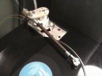
Finally got back to this arm - prompted by also playing with the opus cantus arm. I've only gotten as far as mounting it on a junker tt with an unknown mm cart. It plays although it looks a little "wobbly" or springy. I think playing with the gap might help that.
Next up is to wire it and mount it on the main tt with a proper cart.
Fran
Next up is to wire it and mount it on the main tt with a proper cart.
Fran
Attachments
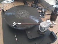
Finally got back to this arm - prompted by also playing with the opus cantus arm. I've only gotten as far as mounting it on a junker tt with an unknown mm cart. It plays although it looks a little "wobbly" or springy. I think playing with the gap might help that.
Next up is to wire it and mount it on the main tt with a proper cart.
Fran
Next up is to wire it and mount it on the main tt with a proper cart.
Fran
Yes, its hollow. I drilled the wood 8mm and then epoxied carbon fibre tube into that. So the arm is a composite - carbon fibre in the middle and cocobolo on the outside. I haven't weighed it.....
Fran
Fran
This is scary - I went back to earlier in this thread where initially I had problems due to the way I did the suspension. Anyway, the freaky thing was my comments were back in sept 2010 - where did all that time go!!
Anyway, I mounted it up tonight and its playing away as I type. Sounds good, no playing issues at all now, although I haven't dug out the test record to check resonances etc. But there's no mistracking etc etc. The other thing thats stopping me from making more comments is that I only have a basic HOMC cart mounted on there (Denon DL160) and it definitely sounds more "etched" that my benz L2. But I'm not ready to mount the benz up yet - I need to make a rest for the arm yet. There's lots of detail there though, and that all bodes well!
I had no issues sorting out azimuth etc and it seems stable all across the record. My comments about the arm seeming a little "wobbly" in my post above can be ignored - it was just that the arm was on a suspended table and the whole suspension was wobbling. Its dead stable on the lenco deck.
I'm sure I have a bit of tweaking yet to do but I would like to express my thanks to Frank for his generosity in sharing the design, but even more so, his practical advice and help to us here.
Fran
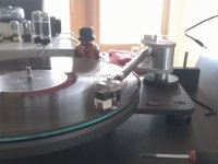
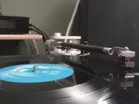
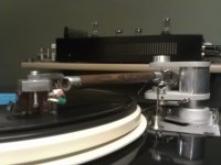
I did another few bits with the arm. The most significant thing was something I remembered frank saying a while back. I decoupled the counterweight. So it now sits on 3 o-rings very similar to how the original rega counterweight was done. The difference in this is not small.
I also made a rest so I can lock the arm when not in use. Makes it a lot safer when kids are about. Anyway I think it's time for a few pics!
I shot a short video that's up on YouTube:
http://youtu.be/U9nncN1E7M4
Fran
I also made a rest so I can lock the arm when not in use. Makes it a lot safer when kids are about. Anyway I think it's time for a few pics!
I shot a short video that's up on YouTube:
http://youtu.be/U9nncN1E7M4
Fran
Attachments
Last edited:
- Home
- Source & Line
- Analogue Source
- DIY Schroeder Tonearm?