Great! Thanks for the quick reply. Onto soldering. No word from Seth on an ETA for the programmed uP.
Thanks to Pyramid, I now have the programmed chip installed and thought I’d update with the troubleshooting I’m doing now.
When I tested the tube output, all Nixies work just fine, and look fantastic. However, the 7 & 8 light at once on all tubes, pointing to an issue with Q7/Q8. I cleaned some of the flux spills and reflowed the solder, tested again last night and everything worked great—7 and 8 flowed separately as they should. However, this morning they are back to glowing at the same time. This makes me think there’s a cold solder joint somewhere, so it’s back to some upkeep on the board, probably suck the old solder out completely, to see if I can fix it.
After that, we’ll be all set to hardwire to the Arduino+IR device. I found a neat push button switch on eBay to control power to both devices, too—I just need to figure out which pins do what on the back of it, because I can’t find a data sheet for it.
If the problem is on all tubes, it might indicate a problem with the transistors. The anode circuit is push-pull, so the anodes should go completely off, but sometimes, a "ghost" appears on some tubes and is not circuit related. Definitely check for leakage via flux etc.
I believe I have extra transistors from the order, so I can try swapping them too. Strange that it would be corrected for awhile yesterday but then revert today. I get a tiny amount of ghosting in the right side of the 5th tube, but the 7&8 issue is different—they stay boldly lit during the time for 7 to light as well as the time for the 8 to light, and it happens on each tube during the sequence.
If you remove the test jumper when it is showing 7/8, the circuit will hold at that state and you can troubleshoot easier. The cathode of the correct digit should be at ground and the gate of that transistor should be near 5V. The other cathodes "float" when not selected, so maybe a mild pull up resistor (220K or higher) to the HV line will correct this?
If there is leakage in one tube between cathode 7 & 8, they are all tied together via the PCB so it will most likely occur in all tubes. If this is the IN12 implementation and you used socket pins, try removing one tube at a time to find the bad one.
If there is leakage in one tube between cathode 7 & 8, they are all tied together via the PCB so it will most likely occur in all tubes. If this is the IN12 implementation and you used socket pins, try removing one tube at a time to find the bad one.
Solved: it was as simple as a few of my leads touching on one of the nixie mounts that I'm using. Everything working well--will post pictures once I get it wired to the tach.
Gosh it’s just so neat. Thanks Pyramid. I’m impressed by the programming and the neat PCB layout.
Nixie tube turntable tachometer: grisly edition - YouTube
Now to build the turntable plinth.
Nixie tube turntable tachometer: grisly edition - YouTube
Now to build the turntable plinth.
@alexkosha - I tried to PM you regarding the availability of a spare PCB but your inbox is full. Please PM me if you still have a spare board available. Thanks!
Thanks to Seth and Bill for the re-up.I now have Nixie chips in inventory. Ready to ship.
The cost for one Nixie chip including shipping and handling is $13.00. Additional chips are $5.00/ea and do not incur additional fees or shipping costs.
Made a mistake today by accidentally plugging in the 24v output for my class D amp into the 12v input of the Nixie board. Now it won’t power on. What did I destroy?
My guess is the 1364 HV supply; it is only rated to 16VDC input.
With 12VDC connected, see if you have a HV (~175VDC) output.
With 12VDC connected, see if you have a HV (~175VDC) output.
Ok the HV is toast—not getting more than 1.5V out. I ordered a new one; hopefully it didn’t take anything else out with it.
Hi Pyramid,
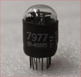
Is any way to utilize some trick or to create some workaround with an extra neon bulb for tubes without decimal point in 3rd position? I have B4032 BURROUGHS - smallest nixie made in US and SWISS, and see if I can utilize these somehow on your tacho. Please let me know.
Is any way to utilize some trick or to create some workaround with an extra neon bulb for tubes without decimal point in 3rd position? I have B4032 BURROUGHS - smallest nixie made in US and SWISS, and see if I can utilize these somehow on your tacho. Please let me know.
Attachments
Last edited:
Your previous answer that I saw here is gone... or it was a ghost massage from my Tapatalk... It is quite buggy software.
So, not need any alterations and just to find some low voltage source on PCB and add LED as separation point between tubes?
So, not need any alterations and just to find some low voltage source on PCB and add LED as separation point between tubes?
Last edited by a moderator:
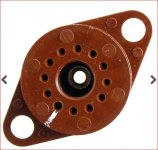
The pin out for the Burroughs tubes are different than the IN12 or IN16 so you will need to use wire leads between the tube and the PCB (or use the Eagle file and modify if for your tubes). The Burroughs tubes have no decimal point, so use a small orange LED with a larger value resistor to dim it (try 2.2K or larger) between 5V and gnd.
Thank you a lot.
No change to Eagle File since I'm going to use dedicated SK-116 tube sockets anyway and need to wire them P2P. I rather to use small neon bulb instead of Orange LED for esthetics reasons (and that is just in case that PSU has enough juice to run both sets, like 5 small nixies and that bulb with Vdrop resistor for 70V operation). If PSU will sag or will be too warm due to excessive current draw, then I'll have no choice and will use advised LED.
No change to Eagle File since I'm going to use dedicated SK-116 tube sockets anyway and need to wire them P2P. I rather to use small neon bulb instead of Orange LED for esthetics reasons (and that is just in case that PSU has enough juice to run both sets, like 5 small nixies and that bulb with Vdrop resistor for 70V operation). If PSU will sag or will be too warm due to excessive current draw, then I'll have no choice and will use advised LED.
Attachments
- Home
- Source & Line
- Analogue Source
- DIY Nixie Tube Display for turntable tachometer