Thanks Warren, i will check all this, mine are similar, fine wire as used by others,
BNTECHGO 38 AWG Magnet Wire - Enameled Copper Wire - Enameled Magnet Winding Wire - 4 oz - 0.0039"
two strands per conductor twisted, and a shield twisted round the twisted signal wires, connected to ground at the connecting box only, no connection, like yours at the cartridge end. only question i have is how close wound is the shield wire, mine is quite open, probably 2 turns per CM to avoid stiffening up the assembly and the shield wraps both channels in one go...............That's about the same as mine, Is yours connected to anything.
Mine is connected to the shield of the phono lead and nothing else.
Mine is connected to the shield of the phono lead and nothing else.
Separate the negative cart and shield at the box and only have them connected together at the phono pre. Having them connected at the phono pre and connection box allows current to flow from the shield to negative between the TT and phono pre. This is not possible with regular RCA leads, which is why I use microphone cable.
Learning all the time!
So, microphone cable has two conductors inside the braided sleeve as opposed to +ve inside and negative the sleeve.
First inclination is to make something with cable i have, but the braided sleeve and some outer covering unnecessarily difficult, so will buy some mic cable, hoping to avoid leaping from the frying pan to the fire, anything will do?
M
Microphones are typically low impedance so microphone cable has no reason to be low-capacitance, although I'm sure you can find that too. Good microphone cable has low microphony which is handy to have with low level signals.
Thanks for that, thinking I might remove a link and wire the cartridge straight into the phone pre and mount that up next to the TT, or is that going to induce more problems than it solves?
My LTA uses Cat6e (the double shielded variety) between the magnet wire and the RCA box. I did this to make removing the carriage easy for R&D purposes. My next setup the magnet wire will go directly to the RCA box.
Good point @Mark Tillotson I actually use AES/EBU cable. On my LCR bridge, my 0.4m cable measures 35pf which is pretty good and lower than most phono cables.
Canare DA206 is available at about 5GBP / meter and it's spec is 75pf/m. If you do go the DIY leads use good quality RCA connectors.
@Mike56 the setup is positive and negative cartridge wires go to the 2 cores, the shield around the magnet wire goes to the shield of both cables. In my setup the shields are connected to the aluminium RCA box so it is also part of the shield. It's important that the negative cartridge lead is not connected to the shield. This will be connected in the phono pre. This setup prevents current flow in the shield which reduces any inductive coupling to the signal wires.
Currently feeling i should wire the cartridge wires directly into the phono pre. I regularly disconnect cartridge wires at the cartridge pins, it's not convenient but familiarity with the tweezers helps! need to remind myself of its grounding arrangements. However, before i do that, what about capacitance, the cartridge will see only the magnet wire before entering the PP?
M
M
Wiring all the way from the cartridge tags to the phonostage in a continuous run does at first glance seem like the best option. Keep the number of solder joints to a minimum.
I take a different approach.
The wire from the tags to the arm base have to be very flexible in order to allow the arm to move freely. This dictates that the conductors have to be very thin. It also severely limits the geometry to a twisted pair/quad or similar.
The wire from the arm base to the phonostage is not limited in these ways.
Running the thin wires from the arm base to phonostage will result in greater loses than those from a couple of solder joints.
I run a thin twisted quad per channel from tags to a set of RCA sockets on the arm base. I'm using Kondo silver. I then can experiment to find the best external interconnects.
What the best interconnects will be is dependant on both the cartridge and the phonostages. What's best on one combination might not work well on another. Unfortunately it's not a one size fits all situation.
Niffy

Many thanks Niffy, that's very useful feedback.
My cartridge connection wires were built to your spec when you were using two strands of magnet wire per connection, so the lead set is 4 connectors (plus and minus for each channel, each twisted pairs) each connector being two strands of magnet wire, the whole lot inside a shield wire of the same composition, not connected to anything at the cartridge end but to ground at the connector box end.
At the moment, the connector box, (a good looking GlenMorangie tin!!) simply connects those cartridge leads to phono sockets, and phono leads connect that to the phono pre. The phono pre is about the same size as the existing box and my thoughts are to reposition the phono pre where the connector box currently sits and to wire the cartridge leads straight into the molex plug that brings the input to the phono pre.
That way there will be no interconnects at all, and the cartridge leads to molex plug will be the only solder joints prior to the phono pre.
But, if it is a but, i believe there will be little capacitive load for the cartridge that way?
I would value advice on that!
By the way, the leads are very un intrusive in the carriage motion.
M
Attachments

The wiring from the cart to the phono stage will form a voltage divider with the load R of the phono stage, so the voltage drop across 2 stands of magnet wire in a 1m length (0.034ohms / m / strand) are effectively Zero. With the low voltage generated by an MM there will not be enough power dissipated by the current flow in the wire to cause the wire to alter in resistance. The bigger issue will be the fragility of the wire, and the PITA of making this cable. Much easier to buy a cable.
Solder connections if done correctly are no issue they are used on every PCB that runs equipment from a simple toy to the detectors on the particle accelerator at CERN. It's audio marketing BS that solder joints cause a degradation in signal especially at audio frequencies, assuming the solder joint is not faulty.
Solder connections if done correctly are no issue they are used on every PCB that runs equipment from a simple toy to the detectors on the particle accelerator at CERN. It's audio marketing BS that solder joints cause a degradation in signal especially at audio frequencies, assuming the solder joint is not faulty.
Hi Mike,
It looks like you are going to have the ideal set up for arm wire by having the phonostage where your connection box currently is.
There is a lot more to cables than just resistance. There is of course inductance and capacitance. Also there is the way the electric and magnetic fields form in the space around the cables and how the dielectric properties of the insulation react with these fields. As anyone who has performed proper cable comparisons can attest cables can make a big difference. I don't believe that the operation of cables is currently fully understood. The differences in sound cannot be adequately explained by today's measurements.
Hi Niffy,I run a thin twisted quad per channel from tags to a set of RCA sockets on the arm base. I'm using Kondo silver. I then can experiment to find the best external interconnects.
Niffy
I do the same when designing my experimental tone arms.
I also design the above wire assembly such that, I can remove the entire wire assembly from the tone arm without the need to unsolder.
That comes in handy when making mechanical design changes.
Sincerely,
Ralf
Many thanks again all!
I am leaning towards this new arrangement.
The wiring is about 20cm long, made as described, a few hours tedious work builds a set!
It will be readily removable because i can simply(!) slide off the cartridge pins and unplug the molex plug at the inputs to my phono pre, provided i make an entry point to the phono pre that a molex 3 pin plug passes through the wire set will then be removable.
However, forgive me please, i am slow on the uptake -
With such a short run, capacitance may be low, can that be a problem and should i do anything about it?
M
If your phonostage has variable capacitance experiment with this. If not I wouldn't sweat it too much. Varying the loading resistance of the phonostage can make quite a big difference. Varying the capacitive loading has very little effect in my experience.
Thanks Niffy and all, the phono pre doesn't have variable capacitance, so it will stay as is! - and i will experiment with the re-wiring!
M
M
I would expect capacitance in such a sort run to be in the order of about 20pf, you can add a capacitor across the pos and neg input terminals of the phono pre.With such a short run, capacitance may be low, can that be a problem and should i do anything about it?
If capacitance is too
 edited error in text as requested by member.
Last edited by a moderator:
I was assuming MC when I wrote this. It might be more noticeable with an MM.If your phonostage has variable capacitance experiment with this. If not I wouldn't sweat it too much. Varying the loading resistance of the phonostage can make quite a big difference. Varying the capacitive loading has very little effect in my experience.
I thought i would report in on the mornings work.........
First i built up courage to chop into my phono pre case and wiring.
2098 attached was before i started this wiring experiment.
The cartridge output wires now go direct into the phono pre which is mounted where the connector box used to be........
I had forgotten how fiddly those tiny wires are.
Its not my best work but it connects correctly, all wiring tested end to end showing continuity and insignificant resistance was a good start.
It plays music, always a good start!
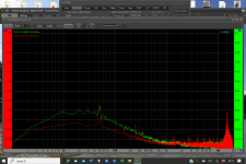
the previous wiring test measurement that caused the suggestion to improve the wiring was 2098.
An equivalent now is 2121.
I haven't done any swapping round etc, i tend to feel that's job done on this aspect? - or would that still be considered poor?
The 50Hz hum is a bit reduced and the signals similar.
By the way that 50 Hz would be instantly recognisable but when connected to the power amp and speakers and at FULL volume, there is no detectable hum, only a tiny amount when i approach the TT.
More later when i have done some tests.
M
First i built up courage to chop into my phono pre case and wiring.
2098 attached was before i started this wiring experiment.
The cartridge output wires now go direct into the phono pre which is mounted where the connector box used to be........
I had forgotten how fiddly those tiny wires are.
Its not my best work but it connects correctly, all wiring tested end to end showing continuity and insignificant resistance was a good start.
It plays music, always a good start!
the previous wiring test measurement that caused the suggestion to improve the wiring was 2098.
An equivalent now is 2121.
I haven't done any swapping round etc, i tend to feel that's job done on this aspect? - or would that still be considered poor?
The 50Hz hum is a bit reduced and the signals similar.
By the way that 50 Hz would be instantly recognisable but when connected to the power amp and speakers and at FULL volume, there is no detectable hum, only a tiny amount when i approach the TT.
More later when i have done some tests.
M
Attachments

- Home
- Source & Line
- Analogue Source
- DIY linear tonearm