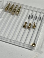
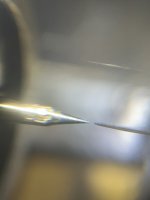
Progress is slow but made headway with grinding my own TC pivots from 1.2mm diameter TC. Mounted the points in brass, loose friction fit and then collet crimped. These were then first passed with 150 grit (green diamond wheel) and then final pass with 400 grit. Then back to the lathe for tip shaping and polish. Comparative measurements of the tip diameter were made by offering up a feeler gauge. Sapphire wheels now have a hole through the centre I’ll post pics soon of these.
Attachments

It will be very interesting to see comparisons Sether. i will be working on Warrens recommendations.
I was completely new to the science(?) of measuring when I started and kind contributors helped me through a getting started process.
I can dig out a version of that tutorial if it helps.
M
I was completely new to the science(?) of measuring when I started and kind contributors helped me through a getting started process.
I can dig out a version of that tutorial if it helps.
M
I am envious of the tools and capability! - always look for the positives, without those i have to find simple solutions!Progress is slow but made headway with grinding my own TC pivots from 1.2mm diameter TC.
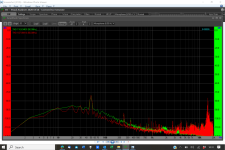
I started this process.my first question is why do you have a difference in level between channels under 1kHz with nothing playing. Swap the inputs to the Behringer if it stays the same the issue is in the Behringer or VA. I don't use VA much but I do know it has customisable filters, make sure these are all bypassed.
Here attached, screenshots of normal wiring and Behringer inputs reversed.
That exonerates the Behringer, so i did the same at the TA output box, same result, so in my opinion it is between the TA output box and the Behringer input.
What is there?
1. leads from output box to phono pre
2. Phono pre
3. leads from phono pre to Behringer.
I have a two battery split supply to the phono pre, i measured the voltages of the batteries and found them different, normally i find the same and i charge quite regularly, charging now, i will report back later.
M
Attachments


Here attached, with thanks to those who helped at the time and apologies if there are errors!Yes please Mike.
M
Attachments

I now continued, charging more equally (ref above) made no difference, and found the difference occurs between the output box of the TA and the input to the phono pre, now I changed those leads for an alternative pair and the levels are more similar, see attached.I started this process.
Here attached, screenshots of normal wiring and Behringer inputs reversed.
That exonerates the Behringer, so i did the same at the TA output box, same result, so in my opinion it is between the TA output box and the Behringer input.
What is there?
1. leads from output box to phono pre
2. Phono pre
3. leads from phono pre to Behringer.
I have a two battery split supply to the phono pre, i measured the voltages of the batteries and found them different, normally i find the same and i charge quite regularly, charging now, i will report back later.
M
Attachments
Then i come back later and they are different again........
i have noticed that when i touch the arm i get a small static click through the speakers, likely related, variable static build up and lead performance?
M
i have noticed that when i touch the arm i get a small static click through the speakers, likely related, variable static build up and lead performance?
M
Hi Sether,
How did you drill the holes in the sapphire wheels/windows?
Have you determined how circular they are?
Have you polished the edges and rounded the corners?
Got any pictures?
Quite exited about this.
Niffy
How did you drill the holes in the sapphire wheels/windows?
Have you determined how circular they are?
Have you polished the edges and rounded the corners?
Got any pictures?
Quite exited about this.
Niffy
Hi Niffy.
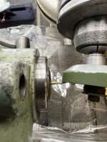
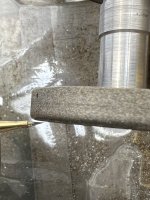
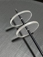
I’ve never worked with anything quite this hard before, a bit daunting a first but ended up being a nice material to work with and extremely predictable. The biggest challenge was how to hold the work piece as a chuck or collet would apply force towards the centre which would result in disaster. Horologists resize watch glass by adhering the window with shellac to a true faced piece of stock held in the lathe. This method is how I plan to edge polish as both edges are chamfered (as I expected for a watch) but only one is finished to the same glassy surface. I used a similar approach to drill the centre hole. I attached the sapphire to a custom workpiece holder which I turned to accurately hold the window, a pre drilled axle hole allows the centre core to be relieved into this void preventing excessive break out. The workpiece holder has two solvent channels leading to a perimeter well, otherwise it would be impossible to remove. Now I have a central hole , I can accurately centre the piece for the edge polishing.
S.
My iPhone camera does some weird editing on macro, the edges of the sapphires are not wobbly!
Attachments
Excellent work.
I assume you used a diamond drill bit with lots of coolant/lubrication.
Are you going to rely on an interference fit between the axle and the hole in the wheel for centering?
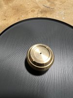
I made the holes in my wheels slightly oversized and then made a couple of jigs, one to measure and one to adjust the position of the wheel on the axle.

This is the only photo I could find which is of my first adjuster.
I assume you used a diamond drill bit with lots of coolant/lubrication.
Are you going to rely on an interference fit between the axle and the hole in the wheel for centering?
I made the holes in my wheels slightly oversized and then made a couple of jigs, one to measure and one to adjust the position of the wheel on the axle.
This is the only photo I could find which is of my first adjuster.
I used a diamond coated bit and water, a lot of patience and kept backing the bit out to clear the hole. The hole was undersized and reamed using the hardened pivot steel with some diamond paste. I’m confident that the hole is within 20 microns, a “gentle” interference fit. Certainly don’t want a forced interference fit with such brittle material. I plan to make a second workpiece holder with a small piece of the pivot steel protruding to centre the wheel and grind the edges.
Centring the wheel is something I need to work on. I either rely on the accuracy of my tools or I may build a jig, as the crucial geometry is pivot tip to tip with the wheel running true between. I’ll have a dry fit play about and see what happens.
I know I haven’t heard a single thing from this LTA yet, but for me part of the enjoyment is in the construction of these crazy puzzles!
S.
Niffy - my congratulation fot that machining device- incredibly clever
Sether - the same - sapphire machining = wow! - turned on a watchlathe+ collets or simply turning the brass support + sapphire weel without removing from chuck?
shellac - ever tried cyano? works fast&fine
carlo
Sether - the same - sapphire machining = wow! - turned on a watchlathe+ collets or simply turning the brass support + sapphire weel without removing from chuck?
shellac - ever tried cyano? works fast&fine
carlo
Hi Carlo, thanks!
The brass workpiece holder was in the lathe (Swiss Emco) held by collets. I did use CA, soaked the part overnight in acetone to dissolve the CA. I think there’s lots of potential in improving the rail/wheel system now that sapphire is on the list of materials! One idea being a monorail with a U shaped sapphire wheel. The issue I have with the two rails is that the gap between them inevitably will vary, even with my rail clamp approach. This together with any discrepancy in wheel alignment will exaggerate “rise and trots” of the carriage. A monorail would reduce this problem. However, I understand that you have taken radically different approaches and superbly engineered creations!! I’m right at the beginning of this journey and enjoying it enormously.
S.
Hi Sether
My wheels have an M3 threaded axle with 5mm diameter hubs that are about 10mm long. One of these hubs is securely attached to the axle with superglue. The other hub can be loosened and tightened.
The set up consist of two jigs. Unfortunately I don't have a photo of the measurement jig, I do still have it somewhere. This has a pair of vees into which the wheel is mounted. There is a leaf spring made from a plastic strip (cut from the lid of an ice cream tub). This spring presses against the edge of the wheel and takes out any play. It also acts as a break so that the wheel can be rotated by hand but will remain in any position set.
Opposite the break is a flat ended M3 grub screw. This grub screw is adjusted so that it just touches the high point on the wheel as it is rotated. I used a strong magnification lens to visually determine this. The location of the high point is marked. I used a very small dot of blutak. The wheel is then rotated by 180°. The grub screw is wound in until it just touches the wheel again and the angle through which the grub screw had to be rotated noted. If you want to get fancy the grub screw could be replaced with a micrometer. The wheel can now be removed from the measurement jig.
The adjustment jig is made in two layers that are bolted together.
The bottom layer has a 5mm hole into which the glued hub is inserted and secured with a grub screw. The wheel is inserted with the blutak mark aligned with the grub screw.
The upper layer has a large hole, bigger than the diameter of the wheel, with 4 M3 flat ended grubscrews protruding into it. A washer raises the wheel so it is at the same level as the grub screws.
(the photo in my previous post was an early version with M6 grubs)
The 4 grub screws are wound in until they touch the edge of the wheel. They need to be just tight enough to prevent the wheel from rotating during the following procedures.
Using a small chuck the free hub is loosened.
The grub screw opposite the blutak mark is backed out by rotating it by half the previously noted angle. The grub screw adjacent to the mark is then tightened by the same amount.
The free hub is then tighten locking the new alignment in place.
The wheel can then be returned to the measurement jig to check again. It took me about 3 attempts before I got it spot on with each wheel. Using this method I reduced the error in centering to less than the error in the roundness of my wheels (~10μm). A long Allen key is useful as the final adjustment involved rotating the grub screws by only a couple of degrees.
I hope this is helpful.
Niffy
That would be most helpful Warren, I’ve ordered a behringer, the same one which Mike pictured. Are all test LPs the same or is there one particular version that I should get hold of? I see that they range from £5 - £50 second hand to new. The knowledge that you guys have is incredible and any guidance as how to interpret the data would be greatly appreciated.
S.
The Ultimate Analog is one that is used by a lot of people. Mine is not concentric and is slightly warped. I also have a few CBS test LP's bought new old stock. I wouldn't recommend buying used test LP's as you have no idea how worn they are. If you do a lot of testing you will wear them out.
Just thought the 2 test signals i use most are 1kHz vertical and horizontal modulation and 300Hz horizontal.
Last edited:
Mike I'd be looking to get the signals identical. The red channel is still slightly down and shows some noise. This could be grounding and this is what I'd suggest you start with. Check the cable shielding. Swap the cables at the output box.I now continued, charging more equally (ref above) made no difference, and found the difference occurs between the output box of the TA and the input to the phono pre, now I changed those leads for an alternative pair and the levels are more similar, see attached.
My DIY cables from the LTA to the phono pre use microphone cable. The 2 cores are + and - signal and the shield is connected to - signal at the phono pre ONLY, the shield is connected to a shield wire (0.08mm magnet wire) I have wound around the wires comming from the cartridge. This shield is NOT connected to the TT or arm/cart, the end of the shield wire wrapped around the cart wires is left not connected to anything.
- Home
- Source & Line
- Analogue Source
- DIY linear tonearm