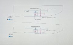
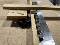
Early stages on this concept.. I was intrigued by the floating tonearm approach earlier in this thread. Where the tonearm is attached to a float which has two wheels running along the walls of the tank. I don’t think I’m alone in thinking that a fish tank next to precious HiFi gear is anything but crazy! However, the low friction offered by this system is appealing. There is another issue being that the tonearm has to be long enough for the tank to be sitting behind the turntable and long tonearms tend to be less stiff than for instance niffys carriage design. I had the idea of replacing the buoyancy force with magnetic levitation. A passive linear neodymium rail could be made to operate in a similar way to an air bearing. However, it is my understanding that the drawback to the air bearing system is that it is completely decoupled from the rail. All the energy generated from the stylus remains in the tonearm, this is the benefit as far as I can see from the rigid coupling of the two wheels, double rail design. Four points of contact allow the energy to drain into the rail and beyond, as with Warren's all aluminium approach. This concept see pics and videos, is a combination of the two. The wheels are turned 90 degrees (low COG) running in some kind of rail, could be vee or rods. This allows the rigid coupling lacking from the air bearing. If the passive levitation force equals that of the carriage then the only force acting on the wheels would be that of the dragging force from the needle in the groove..?? This idea also benefits from a short tonearm design. There is also a potential issue from magnetic interference on the stylus. Perhaps some kind of magnetic shield could be incorporated into the rail and carriage as I say early days! The photos aren’t clear but the mock up carriage is floating, the magnets are way too powerful but it proves the concept.
S.
S.
Attachments
It could play havoc with vertical tracking force.
I did attempt a partially levitated carriage whilst I was still using ball race bearings. The idea being that if I halved the load on the bearings I would halve the lateral friction.
The distance between the opposing magnets, the magnetic gap, wants to remain constant so that the level of repulsion and therefore the level of friction remains constant.
The centre of the magnetic gap want to ideally be at pivot point.
If you try to hold two similarly sized opposing magnets close to each other you will find that they have to be perfectly aligned or they will try to skip off sideways. To counter this one magnet needs to be much wider than the other so that the magnetic field in the gap is consistent.
In my experiment I had a row of 1.5mm wide magnets in between the 4mm rods of the rail. The carriage had two 4mm diameter magnets on adjustment screws. Unfortunately placing magnets between the rails will require wider wheels which will cause vertical friction to dramatically increase if using pin type bearings. This was not a problem with ball race bearings as vertical movement was facilitated by play in the bearing. Placing magnets below the rods would require much stronger magnets. The magnets attached to the cartridge would have to be much greater in diameter to maintain stability.
As the magnetic field will be constant as seen by the cartridge magnetic shielding is not required. Shielding is only required if the magnetic field is modulated.
The partially levitated carriage did not sound as good as when there was no levitation.
This may have been due to several factors.
The advantage of greater coupling outweighed the advantage of lower friction.
The magnetic field probably introduced some form of additional damping resulting in the system being over damped. Eddy damping due to much of the rail structure being metal. The entire rail would need to be non-metalic to prevent this.
The lower load on the ball race bearings might have allowed more bearing chatter.
I didn't persue this idea any further.
Niffy
Last edited:

Very interesting Niffy, I agree vtf could be all over the place unless there is an equal and opposite magnet somewhere else. There are also diametrically opposed cylindrical neodymium magnets which might be suitable. This design however, could be quite well coupled to the rail especially with the vee rail as the wheels are perpendicular to the levitation force. On another note, I’ve ordered some sapphire watch glass wheels.
S.
S.
The biggest issues with maglev are 1) you are introducing a spring which will cause the carriage to bounce vertically, 2) Maglev is unstable unless 1 DOF is restrained which you have done but if the stylus DF is less than the magnetic force the carriage will move backwards.
I have experimented with passive maglev for the platter and CW for a pivoting arm and in both cases I ditched the idea. Maglev as a CW replacement caused the arm to bounce the same will happen if something is levitated. A good example is the JC Verdier bearing being a non-contact maglev affair. There is a modification to add a contact point for rotation to prevent the platter bouncing.
I have experimented with passive maglev for the platter and CW for a pivoting arm and in both cases I ditched the idea. Maglev as a CW replacement caused the arm to bounce the same will happen if something is levitated. A good example is the JC Verdier bearing being a non-contact maglev affair. There is a modification to add a contact point for rotation to prevent the platter bouncing.
Thanks, again very interesting. There’s a few points to the design which I quite like. One being the COG problem is solved. The second being that the effective weight of the carriage could theoretically be zero therefore the frictional force on the wheels is much less. I concur that I did observe a bounce in the system on my mock up. @warrjon do you have any other isolation with your turntables or do you only need the Minus K, what are your recommendations for a DIY approach, three points of contact? Pylons? Etc. I’ve heard good things about the inner tube idea but I cannot see how I could possibly level the rail accurately with this method. As you can tell I’m starting to think about the plinth for my Garrard 401.
S.
S.
Interesting ideas and thoughts.........Floats, air bearings and maglev are all springs, they may be stiff springs, but at what point does that springiness and lack of coupling outweigh any benefits?
Some builders have achieved interesting results with them, others mention this problem.
Interested in the feedback!
Best
Mike
Some builders have achieved interesting results with them, others mention this problem.
Interested in the feedback!
Best
Mike
Hi Sether,
Here is my reason for aligning the pivot point with the magnetic gap.
The repulsive force between two magnets act as a spring.
If the centre line of force between the magnets is not aligned through the pivot you will get some degree of bounce, for instance as in your mock up.
If the line of force between the magnets is aligned through the pivot (for instance both magnets directly above the pivot point) you will get much less bounce. This is because no torque is produced if a force is applied directly through the fulcrum, the only movement vertically is by rotation about the pivot point. No torque no rotation.
Even if the line of force between the magnets is aligned through the pivot point you will still have a problem. And the further away from the pivot point the magnetic gap is the bigger the problem with be. Try holding two opposing magnets close to each other. It's very difficult unless you get them perfectly aligned. As soon as you misalign them by even the smallest amount they try to skit off sideways in the direction of the misalignment. Even a small record warp will cause the magnet attached to the carriage to move relative to those attached to the rail misaligning them resulting in a torque about the pivot point.
This can be alleviated in part by two methods.
Make one magnet much wider than the other. This will result in less change in the magnetic field within the gap and therefore less skitting force will be generated.
The other method would be to place the pivot point in the magnetic gap. This will result in the minimum possible relative movement between the two magnets and therefore the minimum amount of torque about the pivot will be produced. The only movement will be a slight, fraction of a degree, rotation in one axis.
By combining these two methods, as I did in my experiment , the amount of bounce can be reduced to a minimum.
As the rail has a continuous strip of magnets along its entire length the magnetic field remains constant as the cartridge tracks left and right. The bounce problem is only in the vertical plane.
Niffy
Hi Sether,
What I am referring to and the pivot point is in reality the pivot axis and it runs the length of the rail.
This axis has to pass through the magnetic gap. The magnetic gap does not have to be positioned to coincide with where the wheels touch the rail.
In my experiment I had two magnets attached to the cartridge. They were just inbetween the wheels.
Putting them on the outside of the wheels would have been more stable and easier to adjust but would have required outriggers that would have compromised the rigidity of the carriage. Putting the magnets inbetween the wheels is the best place with my style of carriage.
Niffy
Thanks, again very interesting. There’s a few points to the design which I quite like. One being the COG problem is solved. The second being that the effective weight of the carriage could theoretically be zero therefore the frictional force on the wheels is much less. I concur that I did observe a bounce in the system on my mock up. @warrjon do you have any other isolation with your turntables or do you only need the Minus K, what are your recommendations for a DIY approach, three points of contact? Pylons? Etc. I’ve heard good things about the inner tube idea but I cannot see how I could possibly level the rail accurately with this method. As you can tell I’m starting to think about the plinth for my Garrard 401.
S.
Before I had the minus K I used springs under a platform, these worked reasonably well for the very low cost. After this I built a gantry that hung the TT from bungee cord, like isolating an Atomic Force Microscope. Isolating a TT from its environment is key to extracting the micro detail cut into the groove. Most people do not realise a TT has the same resolution as an AFM, if the AFM is not isolated from the environment the image is blurred the same happens with a TT.
You can see the springs under the formply these are set so there is 50% compression with a VERY small bit of foam in the cage to damp the springs from ringing. Here is a link to the testing performed.
https://www.stereonet.com/forums/to...e-isolation-platform/page/19/#comment-4563885
The next gantry worked exceptionally well and isolated the TT down to 0.55Hz, The only issue I never solved was the bungee cords slipping and the
TT losing level. I was lucky and bought a Minus K used from a government lab. The benefit of the minus K over the gantry is the rotational isolation is much higher in frequency so the TT does not rotate


I'd love to try a Minus-k,they are supposed to be the biz.
I have quite a bit of experience with the Townshend seismic sinks and they are very effective. When I was single I used motorcycle inner tubes in between paving slabs. Also very effective and very cheap. I never found leveling a problem, just shift the turntable around until the slab was level. Once leveled they remained level. Now that I am married paving slabs and inner tubes are no longer an option.
My current deck hangs from 3 springs tuned to 3hz. The centre of mass of the suspended part of the deck is aligned exactly with the centre of the 3 springs horizontally and with the lower attachment point of the springs vertically. The suspended portion weighs in at about 20kg. Adjustment is made by adjusting the length of the springs rather than moving the springs. This insures that all 3 springs are tuned to exactly the same frequency and the entire system acts as a single suspension rather than 3 separate ones.
Stand my deck on the floor, a cheap £6 IKEA table or an expensive rack and it sounds exactly the same. The suspension make the deck immune to whatever I stand it on.
Hanging from springs is much better than standing on springs, much more stable and thinner wire section springs can be used.
The crucial thing is to tightly align the centre of mass of the deck with the centre of suspension, both horizontally and vertically.
I think the Pioneer PL-L800 had a similar type of linear track (maglev) which was a combination of passive and active magnet.Early stages on this concept.. I was intrigued by the floating tonearm approach earlier in this thread. Where the tonearm is attached to a float which has two wheels running along the walls of the tank. I don’t think I’m alone in thinking that a fish tank next to precious HiFi gear is anything but crazy! However, the low friction offered by this system is appealing. There is another issue being that the tonearm has to be long enough for the tank to be sitting behind the turntable and long tonearms tend to be less stiff than for instance niffys carriage design. I had the idea of replacing the buoyancy force with magnetic levitation. A passive linear neodymium rail could be made to operate in a similar way to an air bearing. However, it is my understanding that the drawback to the air bearing system is that it is completely decoupled from the rail. All the energy generated from the stylus remains in the tonearm, this is the benefit as far as I can see from the rigid coupling of the two wheels, double rail design. Four points of contact allow the energy to drain into the rail and beyond, as with Warren's all aluminium approach. This concept see pics and videos, is a combination of the two. The wheels are turned 90 degrees (low COG) running in some kind of rail, could be vee or rods. This allows the rigid coupling lacking from the air bearing. If the passive levitation force equals that of the carriage then the only force acting on the wheels would be that of the dragging force from the needle in the groove..?? This idea also benefits from a short tonearm design. There is also a potential issue from magnetic interference on the stylus. Perhaps some kind of magnetic shield could be incorporated into the rail and carriage as I say early days! The photos aren’t clear but the mock up carriage is floating, the magnets are way too powerful but it proves the concept.
S.
Attachments

Making one of the magnetic elements an electromagnet would make making adjustments to the level of repulsion simpler.
My method worked by attaching the magnets on the carriage to grub screws. The disadvantage of this approach is that the centre of the magnetic gap will move as adjustments are made meaning that it will likely not be perfectly congruent with the pivot axis. With an electromagnet the centre of the magnetic gap will remain in a fixed location.
My method worked by attaching the magnets on the carriage to grub screws. The disadvantage of this approach is that the centre of the magnetic gap will move as adjustments are made meaning that it will likely not be perfectly congruent with the pivot axis. With an electromagnet the centre of the magnetic gap will remain in a fixed location.
I'd imagine that the two rails support the base of the arm. The base would be driven across the record, controlled by the servo. This base would support the vertical bearing which would be passive as in any conventional arm.
I'm not a fan of servo controlled arms. Add a lot of complexity to solve a problem that isn't really a problem.
I'm not a fan of servo controlled arms. Add a lot of complexity to solve a problem that isn't really a problem.
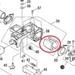
I have no idea about the PL-L1000.I’m trying to get my head around this Pioneer. Is it servo driven? There’s another variant PL-L1000 the pic shows two rails?
S.
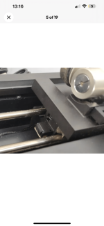
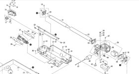
The L800 has a carriage with passive magnets (as seen in the diagram from the service manual) and there is a electromagnet created in the horizontal base tube (this tube has a large diameter - I think around 1.5").
The electromagnet creates a magnetic field by which the carriage floats on the horizontal base tube (without touching it). This is similar to what we see in air floating linear tracking tonearm.
The carriage movement is controlled by a servo driven motor.
I have personally heard this Pioneer PL-L800 turntable and found it far better than the regular linear tracking turntables which I have heard (Technics, Sony, Fisher, etc).
Attachments
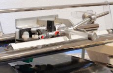
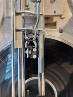
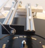
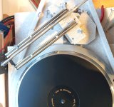
Here is some information on my latest arm, some of you will have seen previous iterations.
They had worked well but I wanted to improve what I considered to be one significant problem, being the vertical lever length that the stylus sees when moving the carriage.
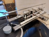
It is a radial arm with the radial motion accomplished by a cart supported by 3 non recirculating ball bearings on parallel rails. This configuration means that gravity keeps everything in firm contact at all times without chatter and without being demanding of close tolerances in build.
In this version the back support rail is higher than the front principal rail so that the cartridge wires can pass under it whilst the rails are as close to the disc as practical.
I have measured the lateral resistance in the same way other contributors have (sine bar) and it is in the area of results that are deemed acceptable.
The vertical motion of the cartridge (warp movement) is enabled by a paralelogram motion (shamelessly borrowed from other peoples work!) supported on the carriage.
These two motions are largely separate, the cart enabling transit radially across the record, coping with eccentricity etc with the stylus on the radius and the vertical motion taken by the paralelogram.
The side load imposed on the stylus to move the cart radially has no lever to add any torque load in the horizontal plane and in this version the vertical lever that that might impose torque is minimised to less than the depth of the cartridge, just 20mm.
This should allow the stylus to track without tracking errors, maintaining that orientation at all times and with minimal loads on the stylus and hopefully able to best reveal what’s in the groove.
It copes comfortably with the torture test of eccentricity and warp in excess of any record playing situation showing little movement of the cantilever.
The result is that using my test cartridge, an AT VM95E to me it sounds better than my bought equipment and better than anything I have built previously and I hope to hear further improvements when my Technics 205 is mounted soon.
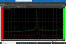
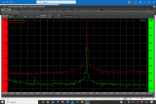
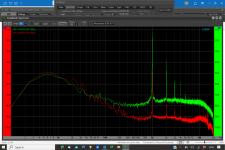
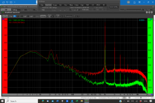
Measurements of a 1000Hz test tone are attached showing the zoomed in area around the tone frequency and the whole spectrum for the tone on each channel, channel separation etc.
The photographs show some of the poor execution and I will go on tinkering and changing, seeking improvements, and will gradually tidy up the execution as I do so (some parts currently are recycled), so all comments and ideas are most welcome!
They had worked well but I wanted to improve what I considered to be one significant problem, being the vertical lever length that the stylus sees when moving the carriage.
It is a radial arm with the radial motion accomplished by a cart supported by 3 non recirculating ball bearings on parallel rails. This configuration means that gravity keeps everything in firm contact at all times without chatter and without being demanding of close tolerances in build.
In this version the back support rail is higher than the front principal rail so that the cartridge wires can pass under it whilst the rails are as close to the disc as practical.
I have measured the lateral resistance in the same way other contributors have (sine bar) and it is in the area of results that are deemed acceptable.
The vertical motion of the cartridge (warp movement) is enabled by a paralelogram motion (shamelessly borrowed from other peoples work!) supported on the carriage.
These two motions are largely separate, the cart enabling transit radially across the record, coping with eccentricity etc with the stylus on the radius and the vertical motion taken by the paralelogram.
The side load imposed on the stylus to move the cart radially has no lever to add any torque load in the horizontal plane and in this version the vertical lever that that might impose torque is minimised to less than the depth of the cartridge, just 20mm.
This should allow the stylus to track without tracking errors, maintaining that orientation at all times and with minimal loads on the stylus and hopefully able to best reveal what’s in the groove.
It copes comfortably with the torture test of eccentricity and warp in excess of any record playing situation showing little movement of the cantilever.
The result is that using my test cartridge, an AT VM95E to me it sounds better than my bought equipment and better than anything I have built previously and I hope to hear further improvements when my Technics 205 is mounted soon.
Measurements of a 1000Hz test tone are attached showing the zoomed in area around the tone frequency and the whole spectrum for the tone on each channel, channel separation etc.
The photographs show some of the poor execution and I will go on tinkering and changing, seeking improvements, and will gradually tidy up the execution as I do so (some parts currently are recycled), so all comments and ideas are most welcome!
Attachments
-
 close up playing.jpg365.6 KB · Views: 179
 -
 Playing (2).jpg423.5 KB · Views: 174
 -
 Playing.jpg458.2 KB · Views: 173
 -
 Rails inner end.jpg342 KB · Views: 179
 -
 rails turned away.jpg700.9 KB · Views: 162
 -
 Screenshot (2075).png143.8 KB · Views: 154
 -
 Screenshot (2076).png150.5 KB · Views: 127
 -
 Screenshot (2077).png160.2 KB · Views: 121
 -
 Screenshot (2078).png160.9 KB · Views: 166
- Home
- Source & Line
- Analogue Source
- DIY linear tonearm