@niffy I’ve found these on eBay, pretty much exactly the correct dimensions, albeit with sharp edges. “Mineral glass” is this a generic term for sapphire watch glass or is it not sapphire? Could drill a hole through with a diamond bit. Might be easier to set it up in a collet on the lathe and offer the hub and pivot up with the tailstock. Use glass glue, the type used on glass tables to adhere a two part hub and pivot assembly.
S.
S.
Attachments

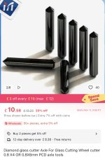
I'm guessing from the expected delivery date that they are not coming from China. It might be worth messaging the seller and asking if it actually is sapphire.@niffy I’ve found these on eBay, pretty much exactly the correct dimensions, albeit with sharp edges. “Mineral glass” is this a generic term for sapphire watch glass or is it not sapphire? Could drill a hole through with a diamond bit. Might be easier to set it up in a collet on the lathe and offer the hub and pivot up with the tailstock. Use glass glue, the type used on glass tables to adhere a two part hub and pivot assembly.
S.
At this price it might be worth taking a punt anyway.
To check you can always refer to our boy Archimedes. The 16.1mm diameter window should weigh 1.62g.

The tip radius looks like it might be a bit on the small side. If the diameter is 0.8mm the tip radius is going to be less than that 0.05mm. If you can round them over a bit they might do the job. The desired tip radius is going to be determined by the cup radius of the vee. Try to keep them to a ratio of 1:2.These also look rather interesting, PCD axles for glass cutting wheels. 0.8mm OD harder than TC.
S.
My pivot radius is 0.125mm and vee 0.25mm. Going smaller would reduce friction but will also reduce the robustness of the bearing. Long term reliability is important.
Niffy
You might find this article interesting. It deals with how two bodies in contact deform and the stresses involved. The most relevant section is the one covering the contact between two spheres. As we are looking at a ball resting in a cup the second Shere is simply modeled as having a negative radius.
https://en.wikipedia.org/wiki/Contact_mechanics?wprov=sfla1
https://en.wikipedia.org/wiki/Contact_mechanics?wprov=sfla1
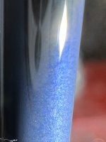
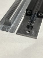
I thought I’d share these photos of polishing the TC rods. The most time efficient method i found was to work through the diamond pastes, the cheap variety from Amazon £11.00. I was sceptical at first but these do indeed contain diamond. Each grade of paste has its own small piece of chamois to avoid contamination. This was clamped with a hand vice together with a piece of corrugated cardboard and a thick piece of leather. Lathe rpm 1500. I noticed an interesting phenomenon when reaching the finest grades 0.5, 0.25, 0.1. The piece started to look blue. Up to that point, the rods had a typical ‘metallic’ appearance, extremely glossy but metallic. What I thought was a high shine was actually the phenomenon of seeing the surface. Moving into the 0.1 final paste ( lubricant water ) I can see INTO the material because the surface is almost invisible. The blue I’m seeing is the cobalt content, looks like the rods contain a ghostly blue nebula!
S.
S.
Attachments
Hi Sether,
I polished my TC rods in a similar way using the same sort of diamond polishing pastes. I used my pillar drill and hand held leather pads. I alternated between spinning the rod in the drill and wiping along its length manually. I gradually worked down to a 0.5μm paste. It took hours to get to the final finish. I didn't notice the blue nebula you have, it is rather beautiful.
I knocked up a test rail so I could compare the lateral friction/rolling resistance of the rods as supplied to post polishing. I used the square edged stainless steel wheels and steel pin bearings in my test carriage for this test. The rods as supplied looked like they had been finished with ~600 grit wet and dry. The lateral friction dropped by almost 20%. Polishing made a big difference.
Niffy
Hi @Mike56 , slowed up a bit over the last couple of weeks…life, work…kids! Sapphire vees arrived from Swiss Jewel which was holding up the project somewhat. Trying to get my head around how to mount them. I see that true point mount them in a 3mm diameter brass stud. However, I recall that the thread pitch is a bit coarse and sourcing fine pitch is difficult. I have some 7BA x 1/4” brass bolts which have a nice fine pitch, just have to see if the head is large enough to accept the vee recess.
S.
S.
I mounted my sapphire vees in aluminium M3 studs. Very fine movements are required for adjustment but are doable.
One piece of advice is do not use a lock-nut to set the studs. The act of tightening will inevitably change the setting. Use a grub screw from the side to lock.
Niffy
One piece of advice is do not use a lock-nut to set the studs. The act of tightening will inevitably change the setting. Use a grub screw from the side to lock.
Niffy
Sether, whilst i don't use jewels, but carbide tips and V screws, its much easier if you have some spring or elasticity at some point.
Its only needed at one end of the pair so one end can be hard coupled and the other end applies a constant spring load to both.
Here is one style

With my paralelogram pivots i use different springs in the same way to allow easy assembly and maintain a reasonable pressure without the risk of overtightening that comes with some alternatives.

In this picture i think you can see the rubber grommets on the cross link that provides the spring on this evolution of my arm........
Of course it can be much better executed but here at least ideas for you!
M
Its only needed at one end of the pair so one end can be hard coupled and the other end applies a constant spring load to both.
Here is one style
With my paralelogram pivots i use different springs in the same way to allow easy assembly and maintain a reasonable pressure without the risk of overtightening that comes with some alternatives.
In this picture i think you can see the rubber grommets on the cross link that provides the spring on this evolution of my arm........
Of course it can be much better executed but here at least ideas for you!
M
Thanks @Mike56 I now see why you need so many pivots! A very interesting design, ceramic balls?..what material are the tubular rails constructed from?
Thanks for the info on the vee bearings mounting, I keep hearing the terminology “end shake” which I interpreted as a small amount of dither. Wouldn’t the end shake be non existent with a sprung bearing, is this beneficial or would it encourage binding?
S.
Thanks for the info on the vee bearings mounting, I keep hearing the terminology “end shake” which I interpreted as a small amount of dither. Wouldn’t the end shake be non existent with a sprung bearing, is this beneficial or would it encourage binding?
S.
Hi Sether,
These tubular rails are 8mm stainless steel tubes, polished through the grades of compounds. This produces a lower friction (starting and running) than the anodised angle (commercially available) that i used before, and is in the region of the low frictions measured and considered desirable/acceptable by others. I have used both ceramic and Delrin balls in this set up. the bright white that you can see in this picture is the ceramic. Delrin may be preferable and when moving the carriage (much faster than ever happens in use) has a softer feel to the motion, but I can neither hear or measure a difference. Clearly there is no chatter available with this arrangement as the contact is maintained by gravity.
Springs and end shake...........having made lots of examples/experiments, if the mounts both ends are stiff it creates a set up where the end pressure adjustment is very critical and can go from partially binding to end shake in the small part turn of an Allen key. I know others use this but I found it too critical, possibly because my parts are not accurate enough, i don't have a lathe etc. Anyway, whatever the reason i have applied a small springiness to one end of my pivots with a variety of methods that gives some tolerance. One end can be rigid and maintains alignment and coupling as well. I have used the grommet mount you see in the picture, a slightly flexible plate mount, a slightly flexible cross beam etc etc, to some extent i believe this is personal preference.
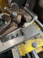
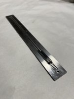
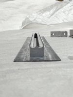
Progress so far on the TC rail, I’ve milled 4mm diameter grooves 1mm into 2mm GFS with a ball nose cutter. The top clamp presses the TC rails into the grooves. On my surfacing plate I noticed that the first rails I purchased were not perfectly true, they were also ground under 4.00mm. This led me to purchase another pair for a different source. These were very accurate across the diameter but still suffered from discrepancy. I’ve come to the conclusion that this is inherent to the manufacturing process of TC. A gentle pressure on the rail while on the surfacing plate is enough to remove the slight bow (0.1mm). Hence this approach of physically clamping down the rails into machined grooves. It will all be epoxied together as per niffy’s.
S.
S.
Attachments
Hi Sether,
That looks like a superbly solid rail.
How is the carriage going to be loaded onto the rail?
My carriage passes both above and below the rail. The end mounting blocks had to be slotted to allow the wheels space to fit.


Niffy
That looks like a superbly solid rail.
How is the carriage going to be loaded onto the rail?
My carriage passes both above and below the rail. The end mounting blocks had to be slotted to allow the wheels space to fit.
Niffy
A detachable carriage stay on the underside. Undecided on the material, could double as the counter weight for the wheels but I need to calculate this first, aluminium, brass strip, thin stainless or carbon fibre?
S.
S.
The main reason why my carriage passes both above and below the rail is that this massively increases carriage rigidity. One of my main design goals was to push the resonant frequency of the carriage as high as possible, out of the audio band. This requires that the carriage has to be extremely rigid.
Passing the rail through the carriage does have the added advantage of lowering the COG of the carriage to be close to the vertical pivot axis. It also acts as a very effective anti-derail mechanism.
If you can design your carriage in this way it will pay sonic dividends.
I did once experiment with a much lighter weight carriage that only passed above the rail. Although the sound of this carriage would still beat most commercial arms it was no match for my more rigid monocoque carriage.
Niffy
Progress so far on the TC rail, I’ve milled 4mm diameter grooves 1mm into 2mm GFS with a ball nose cutter. The top clamp presses the TC rails into the grooves. On my surfacing plate I noticed that the first rails I purchased were not perfectly true, they were also ground under 4.00mm. This led me to purchase another pair for a different source. These were very accurate across the diameter but still suffered from discrepancy. I’ve come to the conclusion that this is inherent to the manufacturing process of TC. A gentle pressure on the rail while on the surfacing plate is enough to remove the slight bow (0.1mm). Hence this approach of physically clamping down the rails into machined grooves. It will all be epoxied together as per niffy’s.
S.
I also had this issue and ended up purchasing a few TC rods before I got 2 that were about 0.01mm. None would roll on the surface plate. I like your clamp idea and if you don't mind I'm going to borrow this idea as we make the new rail.
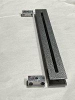
@niffy We've made some tyres from tool steel (pic on left). They have been hardened to 62rc. They will be re-ground to true them up of any distortion from the hardening process, polished then wire cut so the tyre is 2mm high.
The wheels will be aluminium with carbide axles. Total mass of both wheels are about the same as 1 with the carbide tyre.


Hi Warren,
Looks like you've got your wheel design sorted. If they look anything like the rendering they are going to be sweet.
Niffy
Looks like you've got your wheel design sorted. If they look anything like the rendering they are going to be sweet.
Niffy
- Home
- Source & Line
- Analogue Source
- DIY linear tonearm