Azimuth adjustment is important in line contact styli, the longer the contact the more critical it is. Conical does not matter and Elliptical not so critical.
My Stanton 880s runs a Fritz Gyger Signature diamond 5x120um channel separation measures 39dB +- 0.5dB each channel. It's currently in my EPA100, being a removable headshell there is a very small amount of play in the collet, if the headshell is held CCW before tightening I get a 15dB difference between channels in separation.
If the arm has no azimuth adjustment shimming is tedious but pays dividends.
Great to see you guys contributing for us new to the sport on here. Thankyou!
It is only after reading your thoughts that i started measuring things and have some measurements to back up the subjective findings and to guide developments.
Concerning azimuth, i started out without azimuth adjustment and without knowing it had channel separation >10Db unbalanced. I now get it within 1 or 2 Db easily with a simple adjustment like that shown, so definitely worthwhile.
I measure starting resistance and rolling resistance of the carriage on the rails. in my experiments, starting resistance is always higher than rolling resistance, normally by 25-50%. Many rails are around 300mm long and have level adjustment. i started using a bubble level but the run of a (good) cart on its rails is far more sensitive than that, and in my experience can be judged as follows. if raising one end of the arm 1.5mm doesn't consistently start the cart rolling the starting resistance is too high to achieve reasonable performance. Good performance (low resistance) starts at less than 1.25mm and it starts to be excellent at 1mm. i never got below 1.5 with BB's on rails, hence non recirculating balls. Others have calculated the coefficients from this.
I make things more complicated by trying to ensure that in the vertical motion the cartridge also remains parallel to the disc, and this means a different mechanism to the simple pivots others are employing. this concept came from studying little Casey.
When i have got this to the point i consider as good as i can i would be very interested to see comparisons with the simple pivot alternative. Maybe the result will not justify that effort.
Its an interesting thought that pre-echo is a good indicator, i get that on a proportion of discs, on some its more irritating than others!
M
Personally, I think the ball rails have just too high friction and are not easy to control the movements of the balls...........
My advice for anyone who wants to build a mechanical linear arm is that sticking to the basic, put all your effect into the rail design. Your first and last goal is to reduce the friction of the rail.
Interesting how i easily understand your feeling about the balls, i had similar worries until i tried it. However as soon as i had built a reasonably accurate set that all went away. The balls behave perfectly predictably and repeatably and have the lowest friction that i have measured. i haven't done jewelled because of my budget preoccupation!
I agree concerning rails and friction, nothing good will be achieved until you are in the low friction group.
M
Friction can be optimized by using the right materials; please explain why friction is higher than whatever ball bearing?
Balls run (roll) in their V groove in a very controlled manner; they perfectly travel halve the distance the stylus does.
Sliding the arm back after tracking a side, the balls perfectly return (roll back) in their start position.
I have measured recirculating ball bearings compared to non recirculating balls on tracks and could never get the recirculating balls into the low friction zone. If anyone has achieved that it would be useful to see their ideas.
My current best solution uses 8mm stainless steel tube which arrives pretty straight and is inexpensive. A 1m length is around£10-£15. I then spend a couple of hours with my diamond sharpening stone grinding them true before polishing with three grades of mop and polish to a high gloss. These are glued side by side on a flat jig and one has a stiff rail, easily damped with material inside, should look good for years and 6mm ceramic balls run on them really well. this beats glass, anodised etc by a margin and only takes effort, no cost.
Servo linear trackers have noise from a motor and rail to deal with
Hello warrjon,
The tangentially tracking tone arm I designed in the 1980s, used a stepping motor and its rail was only 1.55" long. There was no noise from the motor and there was no noise caused by the carriage traveling on that short rail.
Sincerely,
Ralf
difference?
Now I am curious if you guys see the difference in (ahum) CantiLever deflection between these two videos:
17 sec - YouTube
15 sec - YouTube
In both cases the cartridge/stylus has to deal with 1 mm excentricity.
Now I am curious if you guys see the difference in (ahum) CantiLever deflection between these two videos:
17 sec - YouTube
15 sec - YouTube
In both cases the cartridge/stylus has to deal with 1 mm excentricity.
Last edited:
I have no objection to leaving the azimuth adjustment screw on and would suggest using an aluminum screw if possible because every gram counts for a linear arm.
Now I am curious if you guys see the difference in (ahum) CantiLever deflection between these two videos:
17 sec - YouTube
15 sec - YouTube
In both cases the cartridge/stylus has to deal with 1 mm excentricity.
if you are able to set the camera stable on a stand or something i think it will improve the ability to judge things, M
I measure starting resistance and rolling resistance of the carriage on the rails. in my experiments, starting resistance is always higher than rolling resistance, normally by 25-50%.
M
When starting resistance is an important parameter, why do you use 6 mm balls?
I am working with 3 mm balls which have eight times less mass than a 6 mm ball.
My proto set up works basically well with 3 mm balls, though rolling resistance is the next subject of exploration by using "better" materials.
Yes, difficult to catch the difference in cantilever deflection with a hand held smartphone.
In the second video I had the balls run on two tungsten TIG welding rods (heavy and hard) which slightly improved tracking.
Last edited:
With this type of arm, using non-recirculating bearings, lateral friction is determined by rolling resistance.
I'll use the analogy of pushbike wheels.
Larger balls, like larger wheels, have lower rolling resistance which is why racing bikes have larger wheels. Large wheels will ride over imperfections in the road surface better than small wheels. Likewise larger balls will result in lower resistance.
The most important factor is hardness. Very hard tyres running on tarmac have much lower rolling resistance than soft tyres running on grass. Make both the balls and the rails out of the hardest materials you can. Avoid plastic balls as these are much softer than steel. Ceramic should be better still. Again steel rails will be harder than aluminium with tungsten, or better still, tungsten carbide being harder still. Unfortunately the harder materials are also denser which will be problematic for the arms where the rail moves. The best combination would be ruby balls running on tungsten carbide rails. Unfortunately the hardest materials have a habit of being the most expensive.
Finally, make sure that all surfaces are as smooth as possible. Running slick racing tyres on fine grain tarmac will have lower resistance than nobbley mountain bike tyres on course tarmac. Polishing your rails with 0.5μm diamond paste can make a surprising difference.
Niffy
Thanks Niffy, get that.
When however, as Mike states, starting resistance is important with excentric records (the stylus/carriage has to move back and forth) I can imagine that mass inertia is important. The balls are part of the moving system.
When however, as Mike states, starting resistance is important with excentric records (the stylus/carriage has to move back and forth) I can imagine that mass inertia is important. The balls are part of the moving system.
With this type of arm, using non-recirculating bearings, lateral friction is determined by rolling resistance.
I'll use the analogy of pushbike wheels.
Larger balls, like larger wheels, have lower rolling resistance Polishing your rails with 0.5μm diamond paste can make a surprising difference.
Niffy
Thanks Niffy, get that.
When however, as Mike states, starting resistance is important with excentric records (the stylus/carriage has to move back and forth) I can imagine that mass inertia is important. The balls are part of the moving system.
Evening all, echo Niffy on the pushbike analogy, i started with 5mm becasue i picked it up as an idea somewhere and found the 6mm to measure slightly better. my measurements also varied a lot at that time, i expect because the surfaces were inconsistent.
So i weighed a 5mm and a 6mm ceramic ball, which i use on a 3 or 4 ball carriage and found 0.28 gm difference, so a toatl of around a gram...........
Interested to know how fine the paste Niffy refers to is, i use green blue and yellow on the polishing mops, the finest yellow is this P175 Yellow Menzerna Half Bar | The Polishing Shop
Attachments

Hi daanve,
By lowering rolling resistance you will also lower the starting resistance. As the carriage constantly stop-starts due to eccentricity starting resistance is of utmost importance. When developing the bearings for my arm I made a jig to measure the starting resistance (static friction). This was made so that the force was applied at the same location as the stylus and the test carriage had the same mass as my carriage. I made hundreds of measurements for each iteration of the design. Using harder and smoother materials resulted in lower and more consistent results.
The negative effects of higher lateral mass with linear arms is a myth largely spread by Michael Fremer of stereophile fame (which is a pity as I tend to quite like his reviews). As the frequency at which eccentricity occurs is much lower than the resonant frequency of the cartridge suspension it has very little effect. The deflection of the stylus can be determined to a reasonable level of accuracy using the equation below.
d = Mω^2EC x 1000
Where
d is the deflection of the stylus in microns.
M is the carriage mass in kilograms
ω is the angular velocity of the record in radians/second (3.49 rads/s at 33 1/3 rpm)
E is the eccentricity of the record in metres. This is half the distance the carriage moves back and forth. (A 1mm carriage movement is 0.0005m)
C is the compliance of the cartridge in μm/mN
My main cartridge has a compliance of 22μm/mN and my carriage has a mass of 55g.
On a record where the carriage moves back and forth by 1mm the stylus will be deflected by a maximum 7.37μm due to inertia. The effect of friction is separate to this. The cantilever of my cartridge is about 5mm long. Simple trig shows that this will result in a lateral tracking error of 0.084°. Less than a tenth of a degree. Completely inaudible. The same record will produce lateral tracking error, due to the angle of the groove, of 0.2° at the outer groove rising to 0.38° at the innermost groove. Of course lower levels of eccentricity and lower compliance will result in even lower deflection.
Further to this having a 55g mass, rather than the normally recommended mass of 11.5g for my cartridge, results in over a 12dB reduced in the amount the cartridge body moves relative to the centre line of the groove at audio frequencies. This makes a big positive difference especially in the bass.
Niffy
Last edited:
I should have added that 6mm diameter steel balls compared to 3mm diameter balls would, with the same 1mm record and cartridge, cause a 0.0012° greater tracking error. The increased mass of larger balls has no real effect. The reduction in rolling resistance will have a greater effect in the opposite direction.
Niffy
Niffy
I know this is a pivoting arm but I was asked to post it as the method can easily be applied to the carriage of an LTA.
Background, I am building a 4 point pivoting arm that I bought 4x sapphire Vee's and carbide pivots. An unfortunate mishap damaged one of the carbide pivots so Carlo suggested I try Bic ball point pens. I was not expecting the Bic pivots to outperform the sapphire/carbide but they did.
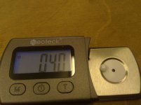
I measured sensitive of the TA with the sapphire pivots which was just under 20mg to commence the arm moving. Bugger me the Bic pivots moved with 8mg.
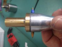
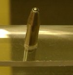
The Bic pivots used regular Bic classic fine pen points in M5 setscrews. The setscrews had nothing done to them no polishing. The ball rotates in the pen seat.
DIY Tonearm sensitivity - YouTube
Background, I am building a 4 point pivoting arm that I bought 4x sapphire Vee's and carbide pivots. An unfortunate mishap damaged one of the carbide pivots so Carlo suggested I try Bic ball point pens. I was not expecting the Bic pivots to outperform the sapphire/carbide but they did.
I measured sensitive of the TA with the sapphire pivots which was just under 20mg to commence the arm moving. Bugger me the Bic pivots moved with 8mg.
The Bic pivots used regular Bic classic fine pen points in M5 setscrews. The setscrews had nothing done to them no polishing. The ball rotates in the pen seat.
DIY Tonearm sensitivity - YouTube
Attachments

Last edited:
Very interesting result Warren, and not a small margin either, less than half.I know this is a pivoting arm but I was asked to post it as the method can easily be applied to the carriage of an LTA.
Background, I am building a 4 point pivoting arm that I bought 4x sapphire Vee's and carbide pivots. An unfortunate mishap damaged one of the carbide pivots so Carlo suggested I try Bic ball point pens. I was not expecting the Bic pivots to outperform the sapphire/carbide but they did.
I measured sensitive of the TA with the sapphire pivots which was just under 20mg to commence the arm moving. Bugger me the Bic pivots moved with 8mg.
The Bic pivots used regular Bic classic fine pen points in M5 setscrews. The setscrews had nothing done to them no polishing. The ball rotates in the pen seat.
DIY Tonearm sensitivity - YouTube
As you know, i use pen tip pivots in my LTA for the paralelogram. They would lead to inconsistent VTF readings if they had much friction and when well set they don't, they are a low friction zero play pivot and beat all the other types that i tried.
Mine have been gel ink ones and i shall now try the Bic type as the ink is a better and longer lasting lubricant.
M
@Mike56
I am planning to splashing out on Fine Parker pen refills. The issue I see with the Bic is the plastic carrier and vibration transfer over the bearing. The Parker refill is steel so energy should pass easier over the pivot.
I am planning to splashing out on Fine Parker pen refills. The issue I see with the Bic is the plastic carrier and vibration transfer over the bearing. The Parker refill is steel so energy should pass easier over the pivot.
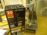
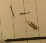
Ever the cheapskate i used these, £10 for 20 and i bought large and small to experiment, only used the larger so far, only problem is these use thinner inks and a wick. the large ones need filing to go inside a 2mm ID tube
M
M
Attachments
Hi Warren,
Interesting results, good to hear that you have managed to reduce the friction of your bearings.
May I ask a couple of questions?
What were the tip and cup radius of the tungsten carbide pivots and vees?
What is the effective length of your arm, how far from the pivot did you apply the force to obtain these results?
With my arm I obtained a starting force of under 10mg using the jewel bearings. In my case the force is applied about 8mm from the bearing pivot as I am using wheels that are about 16mm in diameter. The majority of this force is due to rolling resistance of the wheels on the rail, the force required to rotate the pivot alone is probably in the region of 3mg. If using a long pivoted arm with the force applied at the stylus the required force should be substantially less than this.
The starting TORQUE at the bearing for a pivoted arm will tend to be greater than for my arm as the total supported mass will be higher. The starting FORCE applied at the stylus for a pivoted arm should still be much lower due to the armtube acting as a long lever.
Niffy
I will be interested to see more information and conclusions on this subject to help refine my construction.
I used rollerball tips which i believe used a water based ink, whereas others using oil based inks from ball point pens have successfully retained the ink as lubricant.
Using these could improve my results so i look forward to further info here, thanks, M
I used rollerball tips which i believe used a water based ink, whereas others using oil based inks from ball point pens have successfully retained the ink as lubricant.
Using these could improve my results so i look forward to further info here, thanks, M

- Home
- Source & Line
- Analogue Source
- DIY linear tonearm