As said it's just for fun.
A mental exercise to see if there is a way to get an oscillatory motion to follow effortlessly the eccentricity, directly obtained from it. Normally the force needed to accelerate and brake our not-so-light carriage on eccentricities must be dispersed with frictions on the groove sides + deformation of the elastomer. It would be nice instead to store it in potential energy to be used to our advantage. In reality things are damn complicated, and perhaps more harmful than useful.
Let's start with the pendulum system - composed by the sliding cart + the oscillating mass.
I looked on the net various infos on compound pendulums, sinking among formulas too complex for me, but this one is still different and more complex (two different motions - angular + linear - affecting each other). Perhaps someone skilled with ALGADOO could attempt a simulation, or even dimensioning.
It is clear that a 0.55 hz normal pendulum is too cumbersome, which drives to tilted pendulums (seismic) or to work on the elasticity of a spring.
It remains to understand if the pendulum would tend to synchronize with eccentricity and how this could be tuned, or instead to act in counterphase (as in tuned damped systems, against earthquakes) completely braking the carriage. I think I'll build a mock-up to see what happens.
It would be funny if a small weight on a pianowire could be enough to forget about the eccentricities. Highly improbable, but who knows?
carlo
Last edited:
Hi Carlo,
Interesting idea. It could possibly eliminate or reduce the variation in side force and the resultant LTA errors cause by eccentricity. Fine tuning of the system to match the cartridge would probably be very difficult. If it did work it would have the same effect as an active servo. What it wouldn't do is counter the variation in the groove angle relative to the cartridge that's caused by the record moving backwards and forwards. This angle can easily be as great as that caused by bearing friction and inertia combined. Building a record centering system, as was discussed in this thread a while ago, would be more effective and probably much easier to build. As ever I love your out of the box thinking.
Niffy
Actually with your success in making novel ideas work you probably can make a version of this idea. If you can make the dual cone version of the lil casey with hollow cones you could part fill them with silicone fluid. Selecting the right viscosity and amount of fluid would be key.
Too kind Niffy, just a conversation piece for a relaxing beach chat about "dry" tonearms. Completely agree on the centering devices, if cleverly built
Maybe the tuning concerns only the strict maintenance of the isochrony, while the reaction to the amplitude of the eccentricity, and cartridge compliance should be automatically proportional. Bigger displacement, and bigger acceleration should cause bigger potential energy. (and vice-versa)
I have the feeling that the solution could be mechanically simple but the way to design it very complex: perhaps it would take someone capable of using very powerful mechanical CADs. able to analyze and simulate the complex dynamics of the system.
With such small solicitations to detect, reaching the target by trial and error, diyer's style, seems rather impossible to me.
carlo
This short clip shows a carriage only apparently similar to the one I had in mind.
YouTube
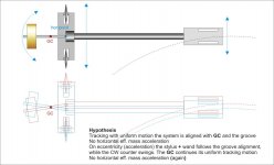
Seeing the center of mass completely motionless (whether the carriage or the pendulum starts the movement is indifferent) suggests that the solution could be even simpler than thought before on #3040.
That is, not to generate passively the motion to follow the eccentricity, but simply moving the parts leaving steady the center of mass.
Maybe it would be enough that on a normal carriage (or even an air bearing) the CW, properly sized, had also an horizontal articulation (not the wand, just the CW) to get that the eccentricities had nothing to do with the mass of the system, but only with its friction (carriage + articulation).
The CW should have a small inclination (horizontal pendulum) for 0.55 hz tuning (or not ?).
What's your opinion, Niffy? (and other friends)
carlo
YouTube
Seeing the center of mass completely motionless (whether the carriage or the pendulum starts the movement is indifferent) suggests that the solution could be even simpler than thought before on #3040.
That is, not to generate passively the motion to follow the eccentricity, but simply moving the parts leaving steady the center of mass.
Maybe it would be enough that on a normal carriage (or even an air bearing) the CW, properly sized, had also an horizontal articulation (not the wand, just the CW) to get that the eccentricities had nothing to do with the mass of the system, but only with its friction (carriage + articulation).
The CW should have a small inclination (horizontal pendulum) for 0.55 hz tuning (or not ?).
What's your opinion, Niffy? (and other friends)
carlo
Last edited:
Hi Carlo,
In the video the pendulum appears to have a period of about a second which means a frequency of about 1hz. This will mean that the pendulums weight is about 248mm below the center of mass of the rotational system. In this case the carriage part of the system can be modelled as a point mass located at the upper bearing as it is rotationally decoupled. There aren't any visual indicators in the video to determine scale but it looks as if the entire carriage/pendulum could be around 300mm tall which would be consistent with the period of oscillation. This is where a problem arrises. In order for the system to have a period of 1.8 seconds, 0.55hz, the pendulum weight would need to be 805mm below the centre of mass of the system. Might be a problem.
Niffy
damn english..... hope this explains better
carlo
It is clear that a 0.55 hz normal pendulum is too cumbersome, which drives to tilted pendulums (seismic) or to work on the elasticity of a spring. #3040
carlo
It is clear that a 0.55 hz normal pendulum is too cumbersome, which drives to tilted pendulums (seismic) or to work on the elasticity of a spring. #3040
Attachments
Last edited:
What we desire is that the motion of the weight is exactly out of phase (-180°) with the motion of the groove so that the motion of the cartridge is in phase (0°). As the driving force from the groove is at the same frequency as the natural frequency of the counterweight/pendulum the motion of this weight will actually be at 90° to the motion of the groove meaning that the cartridge will be moving at -90° relative to the groove. To make matters worse the system will be driven at its resonant frequency. Each revolution of the platter will cause the weight to oscillate further and further. A resonant system driven at its resonant frequency.
Niffy
Niffy
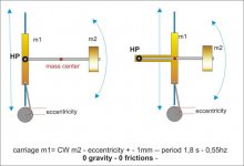
Right Niffy, but is this new one still a pendulum? it can only move on the horizontal plane, so here the gravity has no role, just the masses are acting. Seems a completely indifferent system, driven only by the position of the stylus.
Imagine that both the carriage and the CW pivot are frictionless: when the carriage accelerates-decelerates following the eccentricity, how does the CW behave? Does it remain still by inertia? Rotates in the opposite direction due the energy conservation? And what happens at the mass center?
Would it behave like the pendulum of the video, as if the stylus had the role of the gravity in a real pendulum?
Maybe what happens (period, amplitude) is relative only to the balancing of the system (mass of the cart + mass of the CW + position of the horizontal pivot + position of the rail)
Unfortunately not even one of my few neurons still remembers of Mr Lagrange, and I have absolutely no tools to analyze it. And a practical test needs a highly sophisticated build for sure
carlo
Please, would anyone know how (better, would like) to simulate an inertial system like this in algadoo or similar? if I remember correctly the simulation also analyzes the momentum of the forces in selected points. (Linkage, which I know, works only on geometry)
It would be interesting (for me, at least) to understand what happens also by varying the ratio between the two masses, and /or the position of the horizontal pivot.
thanks in advance - carlo
It would be interesting (for me, at least) to understand what happens also by varying the ratio between the two masses, and /or the position of the horizontal pivot.
thanks in advance - carlo
Attachments
Non tilting
Hi, Carlo. Your last idea is interesting and IMO worth experimenting.
As to Lil Casey, here is a new, non tilting variant, using just double round tubes. Works very well, sliding seems not to be affected by doubling number of balls. More user friendly and easier to adjust, than single tube version.
Walter
Attachments
Walter&Co, congratulations for the new realization, now you are a step forward from me. A non tilting carriage should greatly simplify the initial setup, and also improve the VTA stability. On mine there's no visible movement, but if the cartridge stays firmly in place, it's exactly what it has to do.
Did you use two T carriages in the two tubes? how is going with weights? frictions shouldn't get much worse, eventually put just the balls on the outer side of each cart. More balls than strictly needed may bring chattering. But i don't understand why the little CW is still there.
I'm still looking for a 10x10 or more square carbon profile to try the solution with the bi-cones, while keeping the current weights - maybe I found something in Germany - i'll see-
carlo
The "last idea" seems too good to be true, i have to go deeper. Friend's help welcome
Last edited:
Hi Walter,
Great to see some further development. Are you using 4 balls in the new version? I would have thought that 3 balls, say 2 on the front track and only 1 on the rear, would be the best configuration forming an isosceles triangle. Why does the carriage still need the little counterweight that's positioned in front of the cartridge? If the centre of mass is between the two rails the carriage should be stable without this additional weight. As keeping the overall mass low seems to be a very important factor for this arm loosing the extra weight should be beneficial. I think the two rail version should have a definite advantage as long as its mass doesn't increase to much over the single rail version.
I look forward to hearing your listening impressions compared to the single rail version.
Niffy
I replied before I read Carlo's reply. Looks like we made the same points.
Last edited:
two rails
Hi, Carlo, Niffy. Yes, I thought about the points you mention. It is just another experimental version of Eduard, and not final. Both carriages are T-shape, each with 4 balls. I consider 8 balls are an overkill, and 4 or even 3 of them should be enough. However, current version runs just fine, with no sonic or tracking disadvantages. Mistracking on badly warped or deformed records due to tilt, disappeared. Small CW is there for the purpose to equally adjust load on both rails with different cartridges.
As for me, I would try my own version with two arrow tubes, those are very thin and rigid as well as lightweight. I also will try my new design of spring based counterbalance, which should maintain aqual VTF on warps. All tonearms with CW are prone to pick up rumble, and Lil Casey isn't exception. 15-20dB difference seems attractive to me, no matter how good turntable is. Reducing twice the vertical mass of arm also will not hurt.
Walter
Last edited:
Hi Walter, the solution with 2 arrows may be very good, and very light too using arrows of <5 mm diameter. There are some very stiff around, look for a low "spine"
On the first Lil Casey I had experimented also the Luxo-type spring CW we discussed together: it worked well, but the short spring usable inside the parallelogram made difficult a fine VTF tuning. So try how to implement a long one, or maybe two, with the weak one dedicated only to VTF. Good work, and keep us informed.
carlo
quote Niffy's considerations, precious as usual
Walter&Co, congratulations for the new realization, now you are a step forward from me. A non tilting carriage should greatly simplify the initial setup, and also improve the VTA stability. On mine there's no visible movement, but if the cartridge stays firmly in place, it's exactly what it has to do.
Did you use two T carriages in the two tubes? how is going with weights? frictions shouldn't get much worse, eventually put just the balls on the outer side of each cart. More balls than strictly needed may bring chattering. But i don't understand why the little CW is still there.
I'm still looking for a 10x10 or more square carbon profile to try the solution with the bi-cones, while keeping the current weights - maybe I found something in Germany - i'll see-
carlo
The "last idea" seems too good to be true, i have to go deeper. Friend's help welcome
Square carbon tube should not be hard to find:
Square Standard Modulus Carbon Fiber Tubing \ Rock West Composites
These are in inches.
10mm square carbon tube | eBay
3x3 to 20x20mm Carbon Fiber Square Tube for Quadcopter Drone Frame etc. - Select | eBay
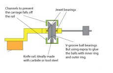
By the way, I think my idea with the knife edge bearing could work.
I tested a small piece of steel sheet with a hobby knife blade as edge and magnetized the steel sheet just a little. This keeps the blade in place and did not affect the friction , as far as I could tell.
Unfortunately I neither have the machinery or the skills to make the bearing with the necessary precision.
It should work. I have been thinking about mechanical linear arm for a while but I just don't feel the urge to make one. Here is my plan. For the total mass of carriage, I would say about 60-70 for a medium compliance cartridge. It is just an estimate. To magnetize the blade may not be a good idea since it may increase the friction.
Attachments
Last edited:
Thanks for the links, Koldby: unfortunately it's more complicated than it seems.
In fact we need a perfectly straight, smooth profile and with a square section inside. This excludes the profiles made from fabric for all the three reasons, apart from the fact that they usually start from 20x20. Those poltruded are OK (if not badly stored) but above 8x8 have rounded, or even round inside sections, unusable with my idea of bi-cones.
Here is the only useful link I could find, with a 10x10x8,5 (too small, maybe) and a 13x13x10 (too heavy, maybe)
Tubes (Square) | R&G Faserverbundwerkstoffe GmbH - Composite Technology
But lets come back to the knife blades, much more interesting. Excellent, as said, but difficult to use with the direction of the forces highlighted in my scheme #3037, and more to the lateral ones during the manipulation. The problem lays in their seats shape, not in magnetizing, imho. A rough mock up may help you to understand the real deal.
The construction of a Lil Casey carbon does not require special tools, only a small circular saw, a pillar drill and a lot of attention (a lathe or a mill is useful, but not indispensable: i have no mill)
Just add some tricks dictated by skill, like cutting - drilling together the pieces of the parallelogram to get them really with the same size, and you are in business.
carlo
Last edited:
bi-cones
Carlo, Eduard have already tried bicone version. It isn't satisfactory because it has much greater friction, than balls. Also bicones are unstable, as they try to tilt, and it is friction that prevents tilting. I have thought about using rollers instead, but now I'm sure they will have the same problems, as bicones. Balls seem to be ideal, they work so great, that using something like air pumps etc. starts looking stupid. In my opinion, Lil Casey design is overally very close to perfection, and with some further improvement will be ideal linear arm.
Something that nobody ever expected is ability working well and sounding amaizing with low, medium and high compliance cartridges. It would be funny for you if you've seen our faces during listeting session. I don't think there is another arm capable of that...
Walter
Last edited:
Eduard have already tried bicone version. It isn't satisfactory....
Really useful news Walter, it must be for that doubt that I had so little desire to build it; you have avoided me an useless trouble, thanks. Niffy did a precise analysis of the different peripheral speeds on the bicone, but I hoped that being so small they were not relevant. I really couldn't imagine the side frictions but, once observed, we have to argue that, even if well balanced, the carriage has to deal with all the residual stylus drag. Now we probably have to re-evaluate the round rail, which with its self-centering effect automatically manages these continuously variable stresses.
It would be funny if you saw our faces during listening sessions. ...
Imagine my at the first listening: laughing alone at the idea that in a hundred years nobody had ever tried such a simple solution, laying under our nose from the disc invention.
carlo
now I'm waiting for your new improvements, you're doing a great job, friends.
I've too several Melodeya LPs: great orchestras and performers, and often superb quality mastering
Last edited:
Yes, now I understand, why Taoist philosophy considers sphere as perfect and even sacral shape. Balls make kind of sacral tonearm.😀
- Home
- Source & Line
- Analogue Source
- DIY linear tonearm